Blood pump systems and methods

a technology of blood pump and pump body, which is applied in the direction of prosthesis, positive displacement liquid engine, liquid fuel engine, etc., can solve the problems of persistent increase in the diameter of the vessel, and achieve the effects of low cost of goods sold (cogs), intermediate duty, and wide operating rang

Active Publication Date: 2017-01-31
ARTIO MEDICAL INC
View PDF153 Cites 16 Cited by
  • Summary
  • Abstract
  • Description
  • Claims
  • Application Information

AI Technical Summary

Benefits of technology

[0014]The present application relates to blood pump systems, including blood pump systems with wide operating ranges, low cost-of-goods-sold (COGS), and intermediate duty times. These blood pump systems are designed for use in a variety of clinical situations and for a variety of clinical indications, as described herein.
[0017]Various types of blood pumps may be employed, including positive displacement and rotary pumps, with rotary type pumps being preferred. In one embodiment, a rotary blood pump system includes a pump having a housing defining an inlet to receive blood and an outlet to discharge blood. The pump housing is designed and dimensioned to house a rotating impeller suspended on bearings. The pump housing can have a first bearing at the inlet portion of the housing and a second bearing at the outlet portion of the housing. Blood enters and exits the rotating impeller, whereby the impeller increases the exit speed of the blood. This increased speed is recovered or translated as increased pressure as the blood decelerates within the pump diffuser, which terminates in the pump outlet.
[0019]In one embodiment, a centrifugal blood pump with pivot bearings includes a pump housing defining a pump inlet having an inflow diffuser to receive blood and direct blood onto an impeller, the pump housing having a top bezel and top pivot bearing extending from a top of the housing into the inlet, and a bottom bezel and bottom pivot bearing extending from a bottom of the housing into the interior space of the housing. The pump also includes the impeller suspended within the housing, the impeller further having a bearing lumen to receive an impeller pivot. The impeller pivot has a first end to engage the inlet portion (top) pivot bearing and a second end to engage the outlet portion (bottom) pivot bearing. In one embodiment, the ends of the impeller pivot are convex and at least one end of each pivot bearing is concave. In another embodiment, the ends of the impeller pivot are concave and the pivot bearings are convex. The impeller can include a variety of fin or blade constructions designed to contact and accelerate blood into the volute. For example, the impeller defines a plurality of blades on the top surface of the impeller and extending radially from a center of the impeller to an outer edge of the impeller. The blades accelerate blood from the impeller's central inlet to its peripheral outlet. In another option, the impeller does not include blades or fins, but does include means to move or propel blood. The impeller optionally includes at least one washout lumen, cut-away, or bore extending generally parallel to a central axis of the impeller from a bottom surface through the impeller to a top surface. The lumen is designed to prevent stagnation of blood under the impeller and around the bottom pivot bearing.

Problems solved by technology

By either method, the system increases the flow of blood in a vessel, which ultimately leads to a persistent increase in vessel diameter.

Method used


Image

  • Blood pump systems and methods
  • Blood pump systems and methods
  • Blood pump systems and methods

Examples


Embodiment Construction

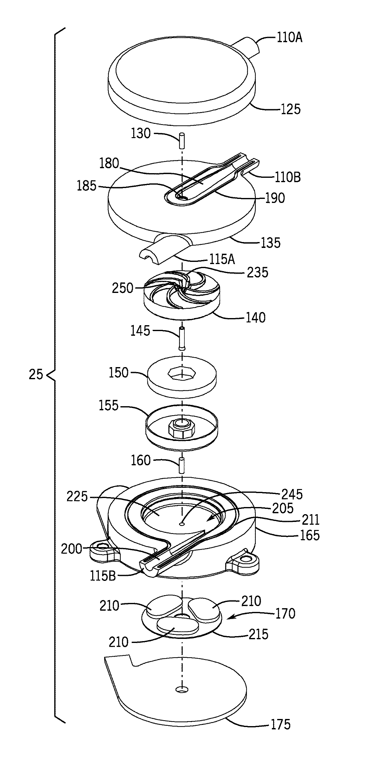
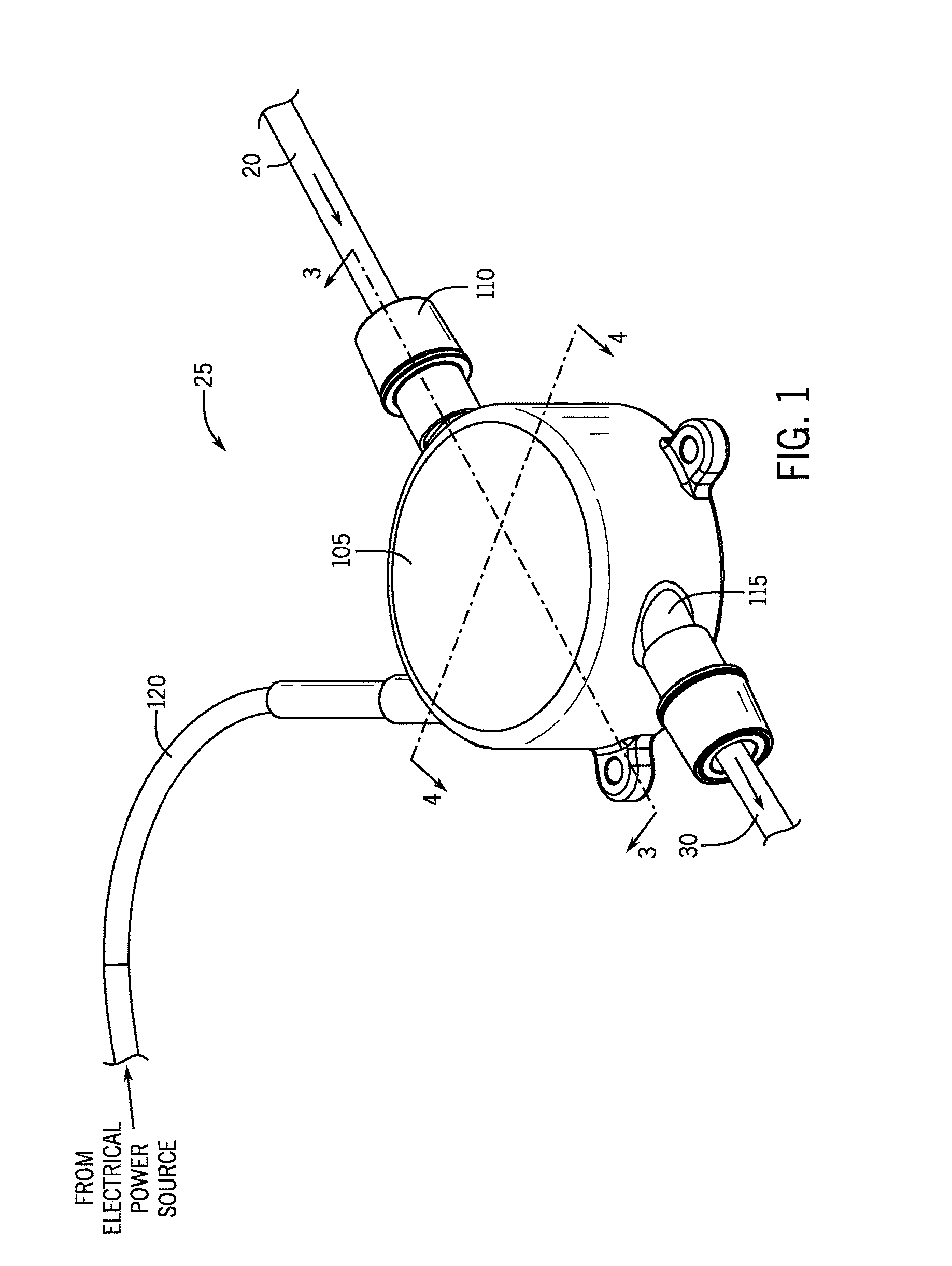
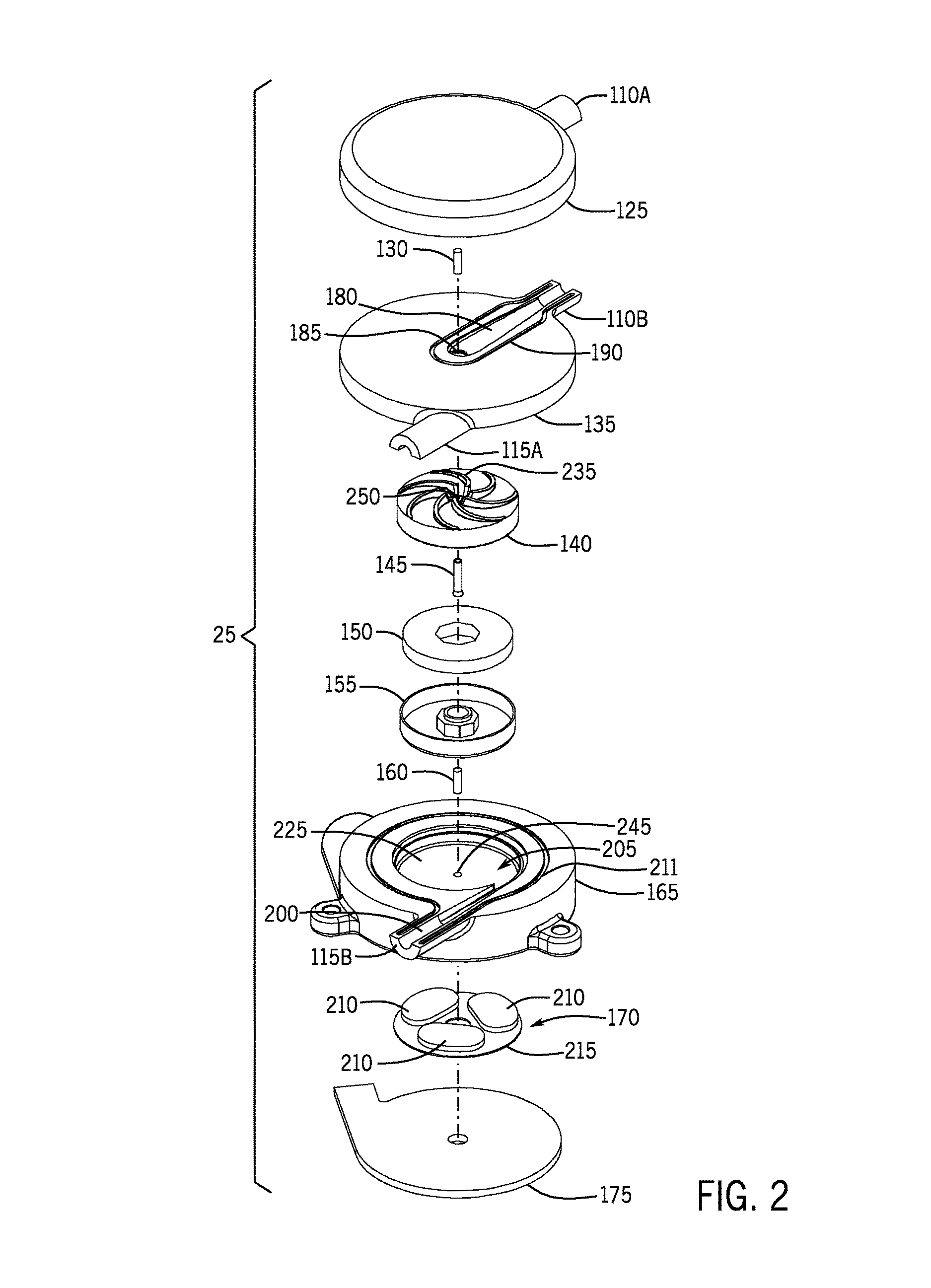
[0096]The systems and components of the present application relate to a blood pump system. In various embodiments, the present application relates to a blood pump designed and dimensioned to discharge blood into a target vessel or withdraw blood from a target vessel in such a way and for such a period of time that the diameter of the target vessel (vein or artery) is persistently increased. Even more specifically, the present application relates to a rotary blood pump system configured to persistently increase the mean and / or peak blood velocity and mean and / or peak wall shear stress in selected segments of veins or arteries for a period of time sufficient to persistently increase the overall diameter and the lumen diameter of selected segments of veins or arteries. The term “persistent increase” or “persistent dilation” when used to describe dilation or an increase in the overall diameter and lumen diameter of an artery or vein, is used herein to mean that even if the pump is turne...


PUM


Abstract

The present disclosure relates to a rotary blood pump with a double pivot contact bearing system with an operating range between about 50 mL / min and about 1500 mL / min, wherein the force on the upper bearing is less than 3N during operating speeds up to 6000 rpm. The disclosure also relates to a method of using a blood pump system for persistently increasing the overall diameter and lumen diameter of peripheral veins and arteries by persistently increasing the speed of blood and the wall shear stress in a peripheral vein or artery for period of time sufficient to result in a persistent increase in the overall diameter and lumen diameter of the vessel.

Description

CROSS REFERENCE TO RELATED APPLICATIONS[0001]This application is a nonprovisional of U.S. Patent Application No. 61 / 684,534 entitled “Blood Pump Systems and Methods”, filed Aug. 17, 2012, a continuation-in-part of and claiming priority to PCT Application PCT / US12 / 50983 entitled “Blood Pump Systems and Methods”, filed on Aug. 15, 2012 which claims priority to U.S. Patent Application No. 61 / 564,671 entitled “Blood Pump Systems and Methods”, filed on Nov. 29, 2011, which is a continuation-in-part of U.S. Patent Application No. 61 / 524,761, entitled “Blood Pump Systems and Methods”, filed on Aug. 17, 2011, and is a continuation-in-part to and claiming priority to U.S. patent application Ser. No. 13 / 030,054, entitled “System and Method to Increase the Overall Diameter of Veins” filed on Feb. 17, 2011, which claims priority to U.S. Provisional Application No. 61 / 305,508 entitled “System and Method to Increase the Overall Diameter of Veins” filed on Feb. 17, 2010, and is related to U.S. Pat...

Claims


Application Information

Patent Timeline
Patent Type & Authority Patents(United States)
IPC IPC(8): A61M1/10A61M1/12A61M5/142F04D29/056F04D29/046A61M1/36
CPCA61M1/101A61M1/1012A61M1/1013A61M5/14236A61M1/1015A61M1/1017A61M1/1036A61M1/3653A61M1/3655A61M2205/3334F04D29/0462F04D29/0465F04D29/0566Y10S415/90A61M2205/32A61M60/824A61M60/422A61M60/148A61M60/232A61M60/531A61M60/814A61M60/221A61M60/104A61M60/523A61M60/538A61M60/226A61M60/515A61M60/165A61M60/825A61M60/419
Inventor FRANANO, F. NICHOLASLOREE, II, HOWARD M.TANSLEY, GEOFFWOODARD, STEVEHUTTO, BARRETT
Owner ARTIO MEDICAL INC
Why Eureka
Try Eureka