Engine device
a technology of engine and exhaust gas, which is applied in the direction of machines/engines, mechanical equipment, pipe elements, etc., can solve the problem of greater transfer resistance of exhaust gas, and achieve the effect of improving connection workability and easy maintaining distan
- Summary
- Abstract
- Description
- Claims
- Application Information
AI Technical Summary
Benefits of technology
Problems solved by technology
Method used
Image
Examples
first embodiment
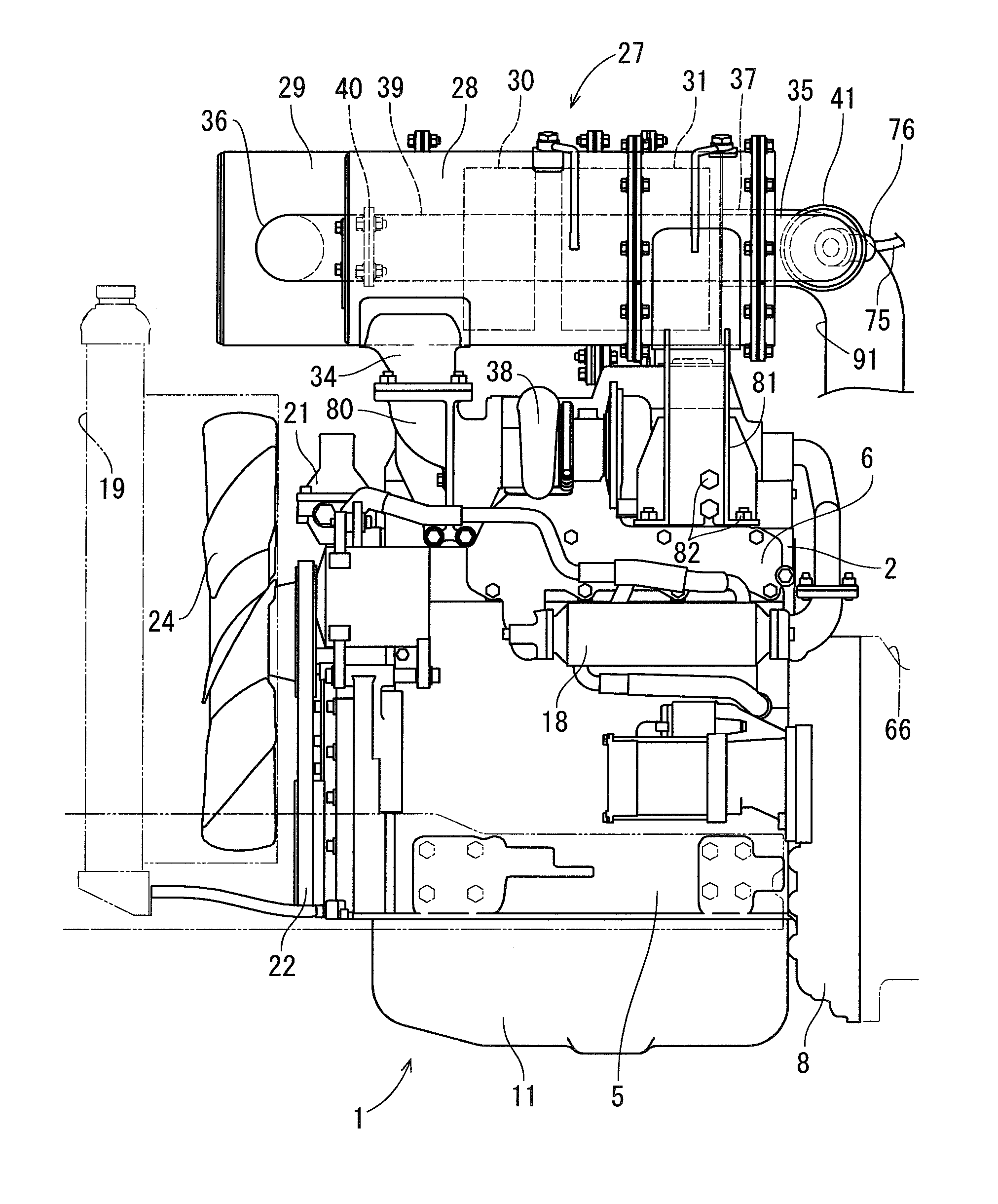
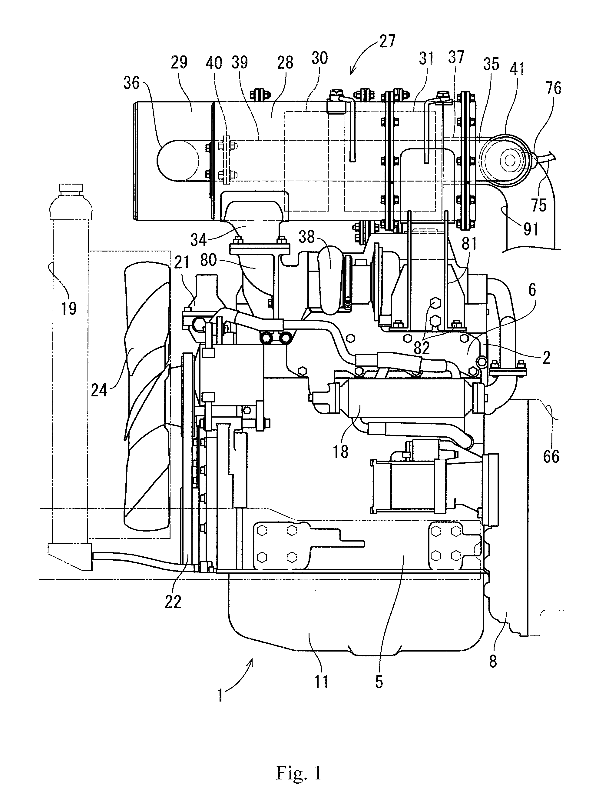
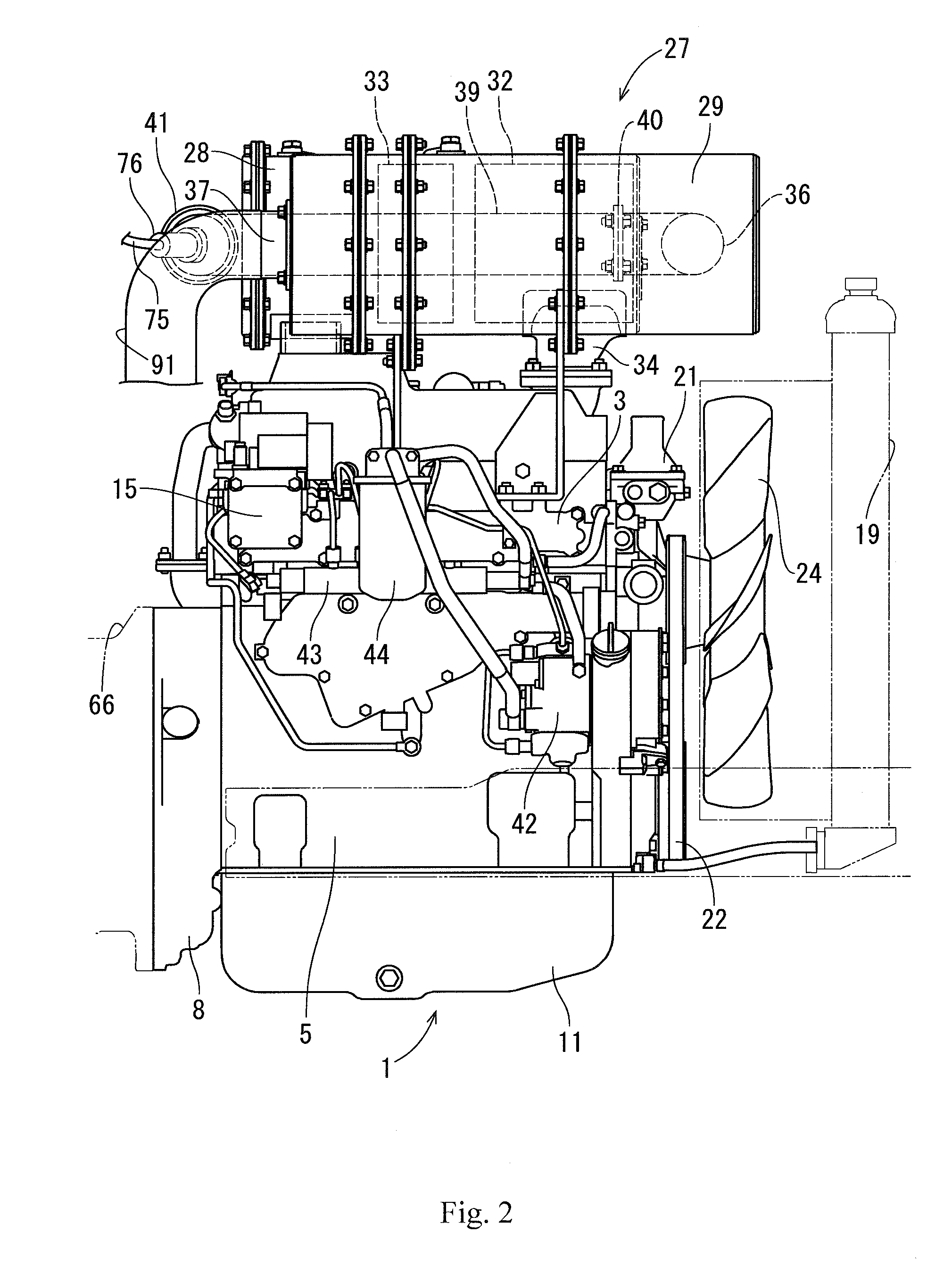
[0073]A description will be given below of a first embodiment obtained by embodying the present invention with reference to the accompanying drawings (FIGS. 1 to 11). FIG. 1 is a left side elevational view in which an exhaust manifold of a diesel engine is installed, FIG. 2 is a right side elevational view in which an intake manifold of the diesel engine is installed, and FIG. 3 is a front elevational view in which a cooling fan of the diesel engine is installed. A description will be given of an overall structure of a diesel engine 1 with reference to FIGS. 1 to 3.
[0074]As shown in FIGS. 1 to 3, an intake manifold 3 is arranged in one side surface of a cylinder head 2 of the diesel engine 1. The cylinder head 2 is mounted on a cylinder block 5 which has an engine output shaft 4 (a crank shaft) and a piston (not shown) built-in. An exhaust manifold 6 is arranged in the other side surface of the cylinder head 2. A front end and a rear end of the engine output shaft 4 are protruded ou...
fifth embodiment
[0112]A description will be given of the fifth embodiment with reference to the accompanying drawings. FIG. 16 is a right side elevational view of a structure in which the intake manifold of the diesel engine is installed, FIG. 17 is a left side elevational view of a structure in which the exhaust manifold of the diesel engine is installed, FIG. 18 is a plan view of the same, FIG. 19 is a front elevational view of a structure in which the cooling fan of the diesel engine is installed, FIG. 20 is a back elevational view of a structure in which the flywheel of the diesel engine is installed, and FIGS. 21 and 22 are perspective views of the diesel engine. A description will be given of an overall structure of the diesel engine 1 with reference to FIGS. 16 to 22.
[0113]As shown in FIGS. 16 to 22, the intake manifold 3 is arranged in one side surface of the cylinder head 2 of the diesel engine 1. The cylinder head 2 is mounted on the cylinder block 5 which has the engine output shaft 4 (t...
sixth embodiment
[0143]Next, a description will be given of a structure of a connection portion between the SCR inlet pipe and the urea mixing pipe showing a sixth embodiment with reference to FIG. 25. As shown in FIG. 25, the outer pipe 86 of the SCR inlet pipe 36 and the outer pipe 88 of the urea mixing pipe 39 are formed by pipes having the same diameter, and the inner pipe 87 of the SCR inlet pipe 36 and the inner pipe 89 of the urea mixing pipe 39 are formed by pipes having the same diameter. A pipe thickness of each of the inner pipes 87 and 89 is formed thinner than a pipe thickness of each of the outer pipes 86 and 88. Further, an end portion of the inner pipe 89 of the urea mixing pipe 39 is fixed by welding to an inner hole surface of the outlet side flange body 93, one end side of a fitting small-diameter pipe 90 is fixed by welding to an end portion of the inner pipe 89 of the urea mixing pipe 39, and the other end side of the fitting small-diameter pipe 90 is inward inserted to the inne...
PUM
 Abstract
Description
Claims
Application Information
 - R&D
- Intellectual Property
- Life Sciences
- Materials
- Tech Scout
- Unparalleled Data Quality
- Higher Quality Content
- 60% Fewer Hallucinations
Browse by: Latest US Patents, China's latest patents, Technical Efficacy Thesaurus, Application Domain, Technology Topic, Popular Technical Reports.
© 2025 PatSnap. All rights reserved.Legal|Privacy policy|Modern Slavery Act Transparency Statement|Sitemap|About US| Contact US: help@patsnap.com


