Materials and methods for thermal and electrical conductivity

a technology of thermal interface materials and materials, applied in the field of carbon nanotubes, can solve the problems of significant problems associated with current thermal interface materials, inability to efficiently dissipate heat, and failure of microelectronic devices to achieve electrical failure, and achieve low electrical

Active Publication Date: 2017-02-07
THE UNIVERSITY OF AKRON
View PDF5 Cites 2 Cited by
  • Summary
  • Abstract
  • Description
  • Claims
  • Application Information

AI Technical Summary

Benefits of technology

[0014]Based on the above, the invention relates to the development of novel structures of free standing metallic carbon nanotube arrays with conformable geometry. These structures are designed to have low electrical and low thermal resistance. The structures are developed as free standing pads with mechanical stability, and the structures are formed over a large area (e.g., 5 cm×5 cm).

Problems solved by technology

As a result, overheating is one of the major causes of electronic failures in microelectronic devices.
But even the best heat sinks cannot dissipate heat efficiently until there is an intimate contact between the processor unit and the heat sink.
However even for the most efficient systems, heat transfer across interface is the bottleneck to enhance heat flow.
Yet, there are significant problems associated with current thermal interface materials.
Being liquid in nature, these materials tend to leak out over a period of time.
This leads to lowered efficiency with respect to time and contamination of the circuit board.
In cases where the conductive particles are added, contamination may lead to short circuiting.
These conductive fillers may reduce overall bulk resistance, but heat transfer across interfaces may not be very efficient since heat transfer may happen via phonons.
The other main drawback of these thermal greases is that their low viscosity at higher temperatures may cause leakage.
Thus, their efficiency may reduce over a period of time.
Such thermal greases are also not suitable for cases where voids are large.
Therefore, removing them from the components may cause some damage.
The disadvantage in such cases is that these materials have different physical properties, e.g. modulus and flow, at different installation and working temperatures.
Thus, it may not be working at its highest efficiency.
Silver filled epoxies may have very high thermal conductance, but these are rigid substances.
If the two bonding surfaces have different thermal expansion coefficients, such rigid areas at the interface may cause damage.
Phononic heat transfer may be ballistic within the bulk of a crystalline solid, but at interfaces phonons may get reflected thus causing low efficiency of heat transfer across an interface.
For commercial use such systems cannot be used.
It is required that the material be available in form of free standing thermal pads; 2) Non-compliable geometries: In many cases the array was not tailored such that it could allow maximum area of contact with the adhering surfaces.
Such geometries not only lead to higher modulus of the whole system (this less intimate contact, leading to higher thermal resistance), but it will also lead to lower thermal conductivity of the whole system; and 4) Low mechanical stability: For commercial use of the material, it is required that they have high mechanical stability.

Method used


Image

  • Materials and methods for thermal and electrical conductivity
  • Materials and methods for thermal and electrical conductivity
  • Materials and methods for thermal and electrical conductivity

Examples


Embodiment Construction

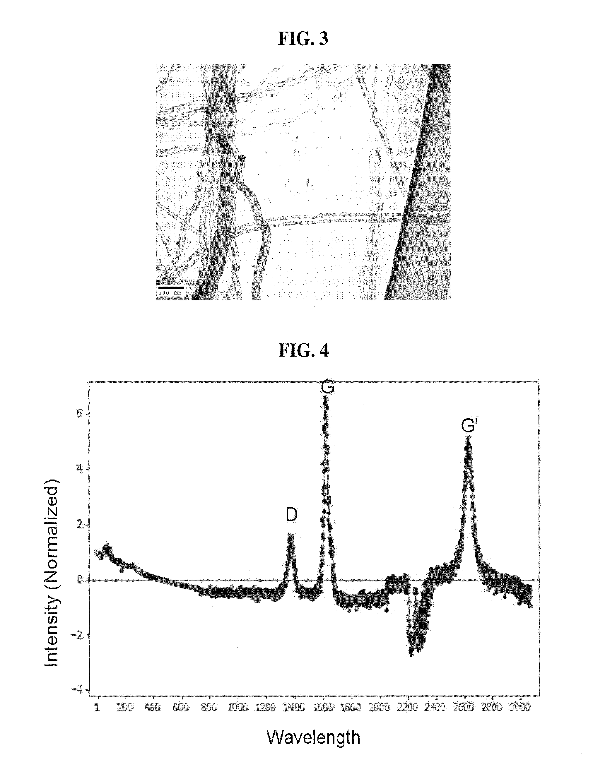
[0033]First, carbon nanotubes (“CNT”) have excellent heat transfer properties. In the present invention, examples of carbon nanotube arrays for use as thermal interface materials will be described, but it should be understood that other carbon nanostructures may also be suitably used. In the invention, the thermal interface materials provide enhanced and efficient heat transport across an interface. There is a relationship between heat transfer, electronic conduction, and adhesion with respect to carbon nanotube type adhesives. The design of a carbon nanotube based thermal interface material (“TIM”) of the present application is based on quantitative studies of mechanical, electrical, and thermal properties of carbon nanotubes. The present invention may be synthesized in geometries suitable for integration with current heat sink systems. In an example, aligned multi-walled carbon-nanotubes (MWCNT) were synthesized to provide characteristics for more efficient heat transfer. In one a...


PUM

PropertyMeasurementUnit
lengthaaaaaaaaaa
thickaaaaaaaaaa
thickaaaaaaaaaa

Abstract

A method of implementing a carbon nanotube thermal interface material onto a heat sink that includes growing carbon nanotubes on said heat sink by chemical vapor deposition and compressing the carbon nanotubes onto metallic surfaces to increase a contact surface area between the carbon nanotubes and the metallic surfaces. The increase in the contact surface area is the area of the carbon nanotubes that is in contact with the metallic surfaces.

Description

CROSS REFERENCE TO RELATED APPLICATIONS[0001]This application claims the benefit of International Patent number PCT / US2010 / 055677 entitled, “Materials and Methods for Thermal and Electrical Conductivity,” which claims the benefit of U.S. Provisional Application No. 61 / 258,640 entitled “Thermal Interface Materials” filed Nov. 6, 2009, and incorporated herein by reference in their entirety.TECHNICAL FIELD[0002]Certain embodiments of the present invention relate to carbon nanotubes. More particularly, certain embodiments of the present invention relate to carbon nanotubes based thermal interface materials.BACKGROUND[0003]The continuing advancement in microelectronic devices has led to tremendous growth in the development of smaller circuit boards and processors having greater speed and computing capabilities. Due to these new developments, the amount of heat generated per unit area in these circuit boards has also increased. As a result, overheating is one of the major causes of electr...

Claims


Application Information

Patent Timeline
Patent Type & Authority Patents(United States)
IPC IPC(8): B32B9/00H01L23/373B82Y30/00C23C16/01C23C16/56C23C16/26
CPCC23C16/01C23C16/26C23C16/56H01L23/373H01L2924/0002Y10T428/2848Y10T428/30H01L2924/00
Inventor DHINOJWALA, ALISETHI, SUNNY
Owner THE UNIVERSITY OF AKRON
Why Eureka
Try Eureka