
Two-high light-emitting diode holder structure

a light-emitting diode and holder technology, applied in the direction of lighting and heating apparatus, printed circuit non-printed electric components association, lighting applications, etc., can solve the problems of long useful life, small amount of power, and not being able to view leds directly, etc., to achieve high degree of mechanical strength and accuracy, easy to view by users, and simple structure

Active Publication Date: 2017-02-07
ILLINOIS TOOL WORKS INC
View PDF13 Cites 2 Cited by
  • Summary
  • Abstract
  • Description
  • Claims
  • Application Information

AI Technical Summary

Benefits of technology

The holder structure enables easy user visibility of LEDs, provides high mechanical strength and accuracy, and is economical to manufacture and assemble, while maintaining a compact and durable design.

Problems solved by technology

Further, they consume small amounts of power and have a long useful life.
However, since the printed circuit board is typically mounted within a chassis of some type the LEDs mounted on the PCB are not usually viewable directly by a user of an electrical system.
If the individual LEDs were directly mounted on the SMT printed circuit boards using the “through-holes”, there would be encountered a number of disadvantages associated with this technique.
Secondly, after the use of radiant heating for securing the other electrical components to the board another step would be needed to secure the individual LEDs to the board by way of “wave soldering”.
These required extra steps are very expensive and would thus increase the manufacturing and assemble cost of the boards.
However, the conductive leads usually provided for the individual LEDs tend to be very pliable and narrow so as to be unable to support and accurately locate them very high off the board or near the edge of the board.

Method used


Image

  • Two-high light-emitting diode holder structure
  • Two-high light-emitting diode holder structure
  • Two-high light-emitting diode holder structure

Examples


Embodiment Construction

[0034]Before explaining at least one embodiment of the invention, it is to be distinctly understood at the outset that the present invention shown in the drawings and described in detail in conjunction with the preferred embodiments is not intended to serve as a limitation upon the scope or teachings thereof, but is to be considered merely as an exemplification of the principles of the present invention.

[0035]As such, those skilled in the art will appreciate that the conception upon which this disclosure is based may readily be utilized as a basis for the designing of other structures, methods and systems for carrying the several purposes of the present invention. It is important, therefore, that the claims be regarded as including such equivalent constructions insofar as they do not depart from the spirit and scope of the present invention.

[0036]The invention will now be described with reference to the figures in the accompanying drawings, in which like reference numerals indicate ...


PUM


Abstract

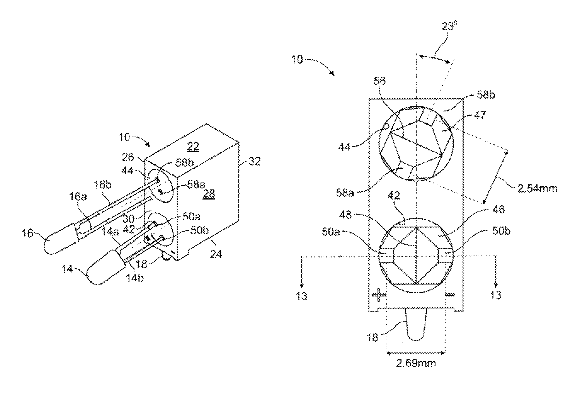
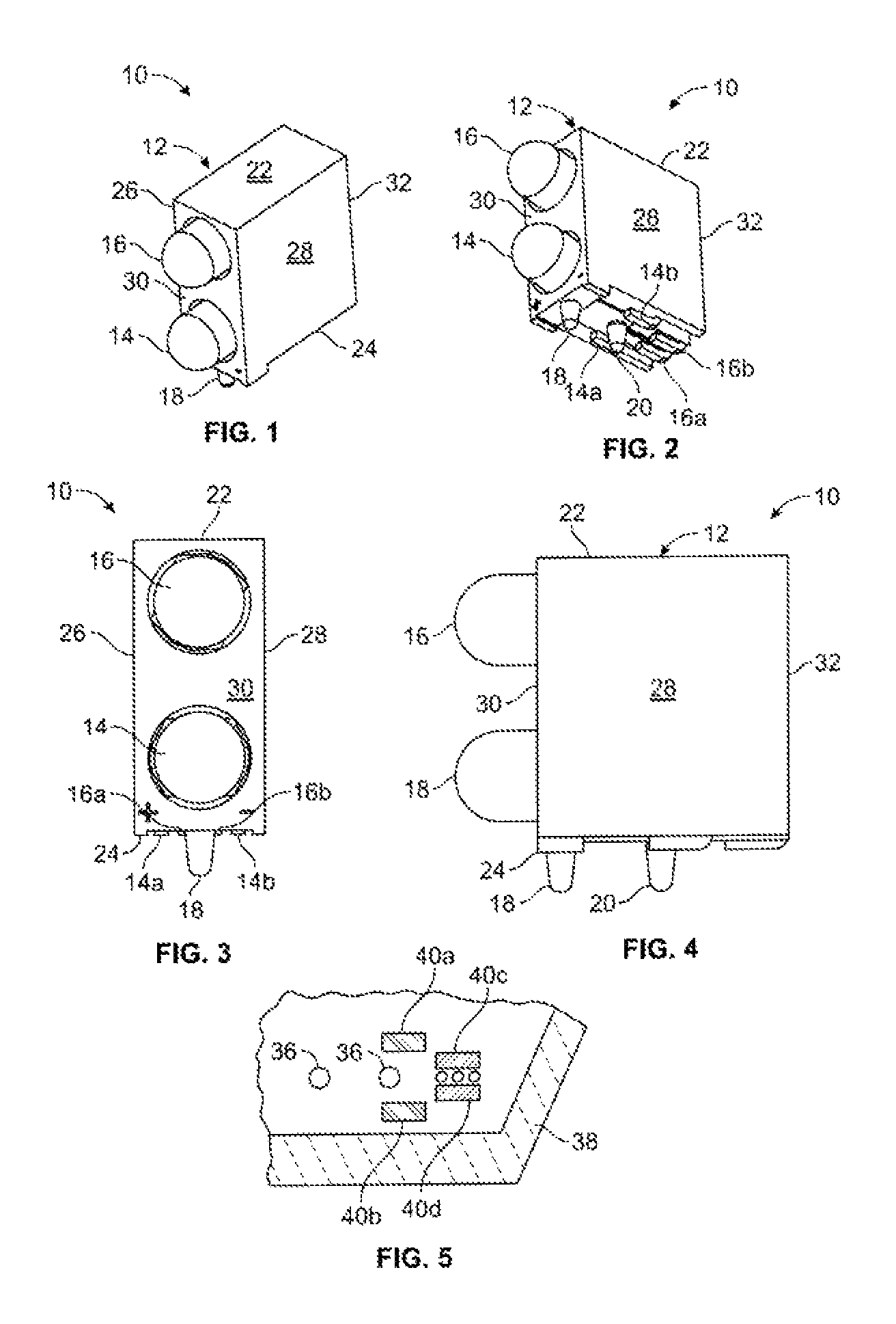
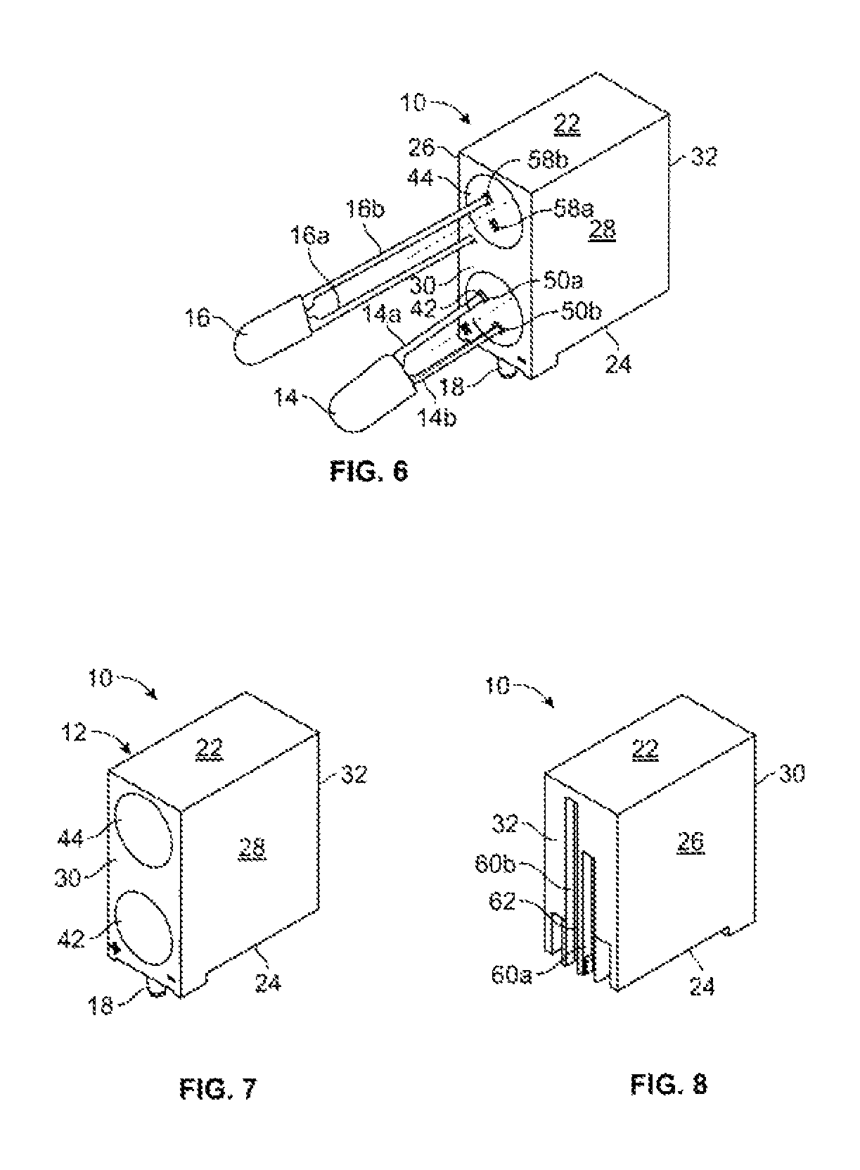
A holder structure for mounting light indicators on printed circuit boards using surface mount technology at a position elevated above the surface of the board is provided with a body member including a top wall, a bottom wall, opposed sidewalls, a front wall, and a rear wall, all being formed integrally together. Two spaced-apart recesses are formed and aligned vertically in the front wall of the body member terminating in respective first and second interior wall portions. The first interior wall portion has openings formed on diametrically opposed sides of a vertical partition and lying in a horizontal plane parallel to the bottom wall. The second interior wall portion has openings formed on diametrically opposed sides of a transverse partition and lying in a plane which is rotated a predetermined number of degrees from a vertical plane perpendicular to the bottom wall.

Description

BACKGROUND OF THE INVENTION[0001]1. Field of the Invention[0002]This invention relates generally to indicator apparatuses or structures for mounting indicator lights on printed circuit boards. More particularly, it relates to a holder structure for mounting light-emitting diodes (LEDs) on printed circuit boards (PCBs) using “surface mount technology” (SMT).[0003]2. Description of the Prior Art[0004]As is generally known to those skilled in the art, light-emitting diodes (LEDs) are particularly useful as status indicators for various types of electrical circuits and systems, such as in different kinds of proximity sensors for detecting the presence or absence of an object. For example, one or more LEDs may be mounted at a sensor housing so as to provide desired information about the operating condition of the sensor at the housing. The LEDs are very advantageous in this type of operating environment due to the fact that they are small in size and are relatively inexpensive in cost. F...

Claims


Application Information

Patent Timeline
Patent Type & Authority Patents(United States)
IPC IPC(8): F21V19/00F21V23/06F21V23/00H05K3/30H05K1/18H05K3/34F21W111/00F21Y101/00
CPCF21V19/002F21V23/005F21V23/06H05K3/301F21W2111/00F21Y2101/00H05K1/181H05K3/308H05K3/3421H05K2201/0311H05K2201/10106H05K2201/10606H05K2201/10651H05K2201/10757F21Y2115/10
Inventor AHMED, YASOOBSIEVERS, STEVEN
Owner ILLINOIS TOOL WORKS INC
Learn More