System for laser-based digital marking of objects with images or digital image projection with the laser beam shaped and amplified to have uniform irradiance distribution over the beam cross-section

Active Publication Date: 2017-02-14
VARDEX LASER SOLUTIONS
View PDF12 Cites 8 Cited by
  • Summary
  • Abstract
  • Description
  • Claims
  • Application Information

AI Technical Summary

Benefits of technology

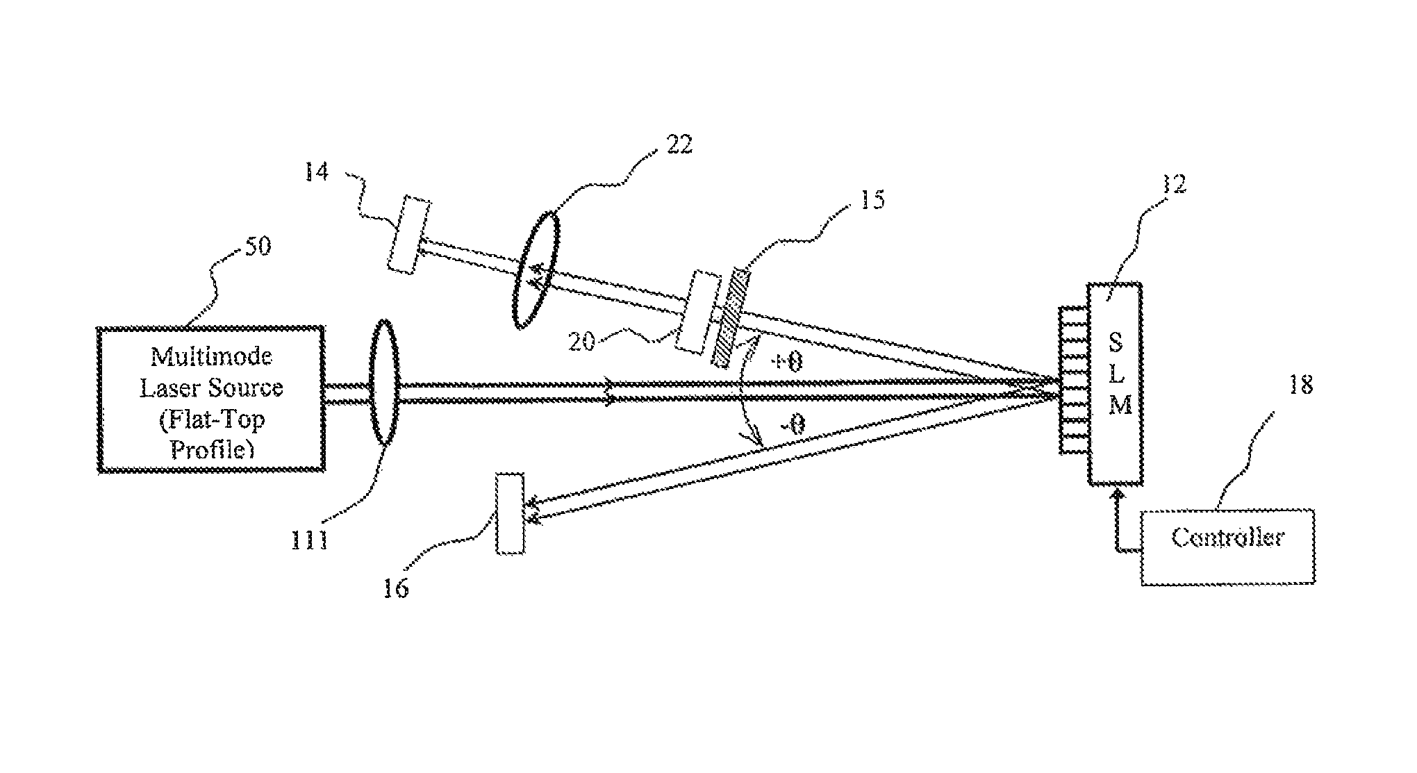
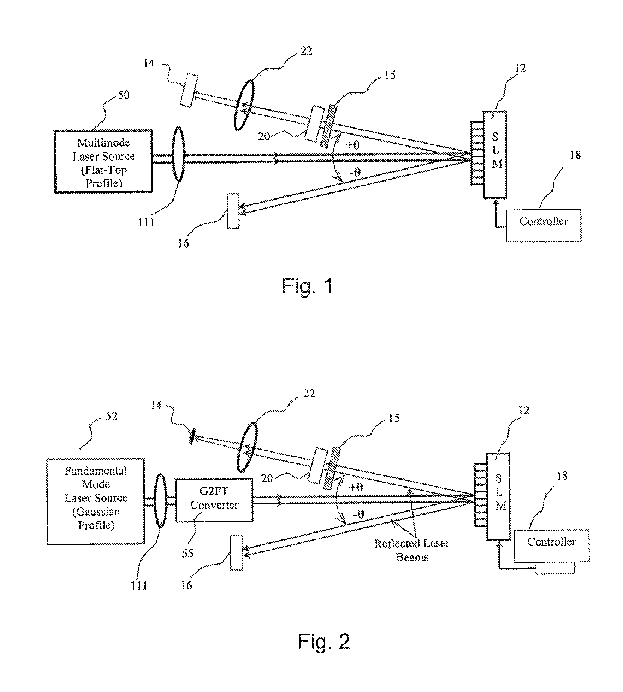
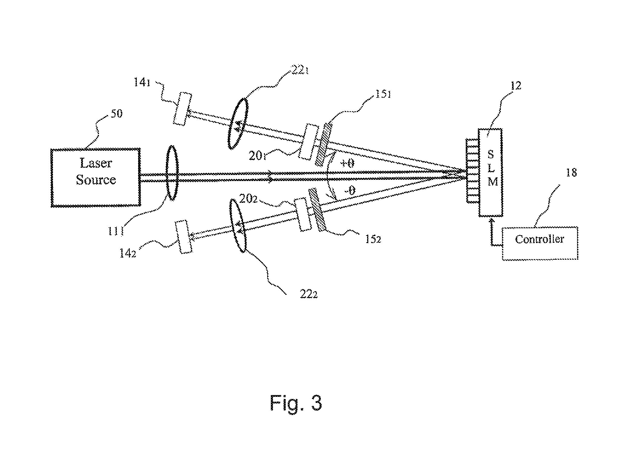
[0008]An optical image amplification system comprises a laser apparatus configured to supply a laser beam having a non-Gaussian irradiance distribution over a beam cross-section, wherein the non-Gaussian irradiance distribution of the laser beam comprises a substantially uniform irradiance distribution over the beam cross-section. The system further comprises a spatial light modulator optically coupled to receive the laser beam, wherein the spatial light modulator is controlled to generate an output laser beam comprising an optical pattern across the beam cross-section to perform a laser material processing operation to mark a target object with an image or a pattern. Also included is an optical-conditioning system configured to capture a propagating diffracted beam of the optical pattern and to form at least one of a magnified version and a demagnified version of the optical pattern and to control

Problems solved by technology

Although the technology has made advances in terms of speed and performance, placing a 2-D bar matrix code or a high resolution image on the object can be challenging.
However, certain drawbacks can arise during their operation.
However, the overall power cannot be increased indefinitely and is limited by the damage threshold of the SLM.
The system described in the foregoing patent, however, is somewhat impractical since the physical dimensions and the cross-sectional area of available micromirror devices are relatively small (in the order of few square cm).
That is, the irradiance of the incident laser beam cannot be reduced by a factor greater than L. Any further magnification (M>L) would result in part of the beam to miss the device.
Thus, in practice, Applicant believes that the marking system proposed in the foregoing patent would not be effective for applications requiring optical intensities L times higher than the DMD damage threshold.
Also, in applications where large sized marks are required, with mark size being comparable to the size of a DMD/SLM itself, Applicants submits that the beam expansion and contraction mechanism would be useless.
As a res

Method used


Image

  • System for laser-based digital marking of objects with images or digital image projection with the laser beam shaped and amplified to have uniform irradiance distribution over the beam cross-section
  • System for laser-based digital marking of objects with images or digital image projection with the laser beam shaped and amplified to have uniform irradiance distribution over the beam cross-section
  • System for laser-based digital marking of objects with images or digital image projection with the laser beam shaped and amplified to have uniform irradiance distribution over the beam cross-section

Examples


Embodiment Construction

[0040]In accordance with one or more embodiments of the present invention, systems and techniques for laser-based marking are described herein. In the following detailed description, various specific details are set forth in order to provide a thorough understanding of various embodiments of the present invention. However, those skilled in the art will understand that embodiments of the present invention may be practiced without these specific details, that the present invention is not limited to the depicted embodiments, and / or that exemplary embodiments of the present invention may be practiced in a variety of alternative embodiments. In other instances, methods, procedures, and components, which would be well-understood by one skilled in the art have not been described in detail to avoid unnecessary and burdensome explanation.

[0041]Furthermore, various operations may be described as multiple discrete steps performed in a manner that is helpful for understanding embodiments of the...


PUM


Abstract

An optical system including a laser apparatus, a spatial light modulator to receive a laser beam, an optical-conditioning system to capture a propagating diffracted beam of the optical pattern and to form at least one of a magnified version and a demagnified version of the optical pattern and to control a quality of the optical pattern, a uniformity maintaining optical amplifier to receive the laser beam output from the spatial light modulator and generate an amplified laser beam such that a final optical pattern is an amplified version of the optical pattern as generated by the spatial light modulator, the amplified laser beam having a substantially uniform amplification across the cross-section of the beam, and at least one of a time-bandwidth pulse duration control mechanism including at least one of a pulse stretching element and pulse compression element, and a frequency conversion device.

Description

CROSS-REFERENCE TO RELATED APPLICATIONS[0001]This application is a Continuation-in-Part of U.S. application Ser. No. 13 / 206,189 filed Aug. 9, 2011, which claims the benefit of U.S. Provisional No. 61 / 372,197 filed Aug. 10, 2010, and is incorporated herein by reference in their entirety.FIELD OF THE INVENTION[0002]The present invention is generally related to laser image amplification marking systems, and, more particularly, to a system comprising a laser beam-shaping arrangement to have a spatially uniform irradiance for the initial beam, a Spatial Light Modulator (SLIM) and an optical amplifier configured to provide an amplified beam having a spatially uniform irradiance.BACKGROUND OF THE INVENTION[0003]It is known that optical representation of data, such as machine-readable bar codes, logos, etc., can be attached, placed or marked on products by various means, such as industrial ink-jet printing, electrolytic chemical etching and laser markings. The data can serve multiple purpos...

Claims


Application Information

Patent Timeline
IPC IPC(8): H01S3/00G02B27/09G02B3/00
CPCH01S3/0085H01S3/0057H01S3/0092G02B27/0927G02B3/0087B41M5/26B41J2/442B41J2/455B41J2/465B41J2/47G02B27/0994
Inventor GHAURI, FARZANUMAR, MOHAMMAD
Owner VARDEX LASER SOLUTIONS
Why Eureka
Try Eureka