Supercharge Your Innovation With Domain-Expert AI Agents!

Laser oscillator including fans which cool resonator unit

a technology of laser oscillator and resonator unit, which is applied in the field of laser oscillator, can solve the problems of difficult to raise the temperature of the resonator unit, the fan may not be operated, and the laser oscillator may not become usable after a certain tim

Active Publication Date: 2017-02-14
FANUC LTD
View PDF6 Cites 0 Cited by
  • Summary
  • Abstract
  • Description
  • Claims
  • Application Information

AI Technical Summary

Benefits of technology

This solution shortens the time to become operational after activation or restart at low temperatures, stabilizes the resonator unit's temperature, and reduces power consumption by optimizing airflow direction and volume based on temperature differences.

Problems solved by technology

Further, since only a little heat is generated by the resonator unit, the fans may not be operated when the interior of the housing may not be cooled.
In other words, as a problem, it takes a certain time for the laser oscillator to become usable after the activation of the laser oscillator.
When the conventional water-cooled laser oscillator is employed as a laser processing machine, cold air in the housing is blown to the resonator unit during the above-mentioned warm-up operation, so it becomes difficult to raise the temperature of the resonator unit, contrary to the intention.
This also results in the prolongation of the warm-up time.
This poses still another problem: the operation of the laser oscillator is unstable until the temperature of the resonator unit reaches a steady state upon a transition of the laser oscillator from a standby state to a ready-for-laser machining state.

Method used


Image

  • Laser oscillator including fans which cool resonator unit
  • Laser oscillator including fans which cool resonator unit
  • Laser oscillator including fans which cool resonator unit

Examples


Embodiment Construction

[0034]An embodiment of the present invention will be described below with reference to the accompanying drawings. Although the following description assumes a fast speed axial flow-type gas laser device as an exemplary laser oscillator, the present invention is not limited to this.

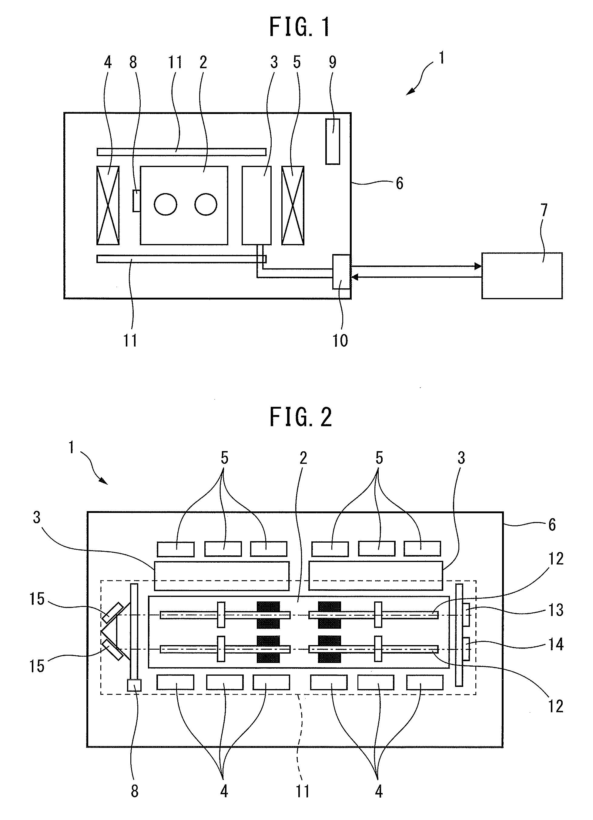
[0035]FIG. 1 is a front view schematically illustrating the configuration of a laser oscillator according to an embodiment of the present invention.

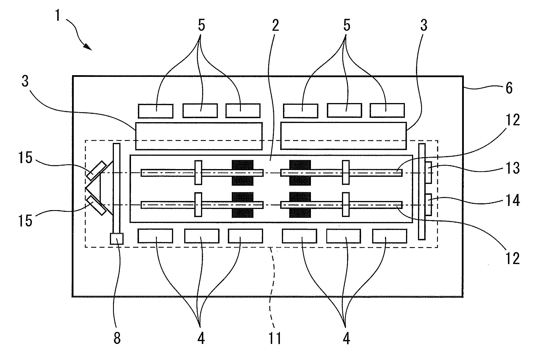
[0036]A laser oscillator 1 according to this embodiment includes a resonator unit 2 for resonating a laser beam to be output, heat exchangers 3 located adjacent to one end of the resonator unit 2, and first fans 4 and second fans 5 respectively located at two opposite positions across both the resonator unit 2 and the heat exchangers 3.

[0037]The laser oscillator 1 further includes a housing 6 which accommodates and protects the resonator unit 2, the heat exchangers 3, and the fans 4 and 5. A chiller 7 which supplies cooling water being controlled at a constant ...


PUM

PropertyMeasurementUnit
temperatureaaaaaaaaaa
resonator temperature measuring unitaaaaaaaaaa

Abstract

A laser oscillator according to this invention includes a resonator unit, heat exchangers, fans, a resonator temperature measuring unit, and a fan control unit. The resonator unit resonates a laser beam to be output. The heat exchangers are arranged adjacent to the resonator unit and are to be supplied with a cooling liquid. The fans are arranged at least at one of two opposite positions across both the resonator unit and the heat exchangers and generate airflow in one direction, which passes through both the resonator unit and the heat exchangers. The resonator temperature measuring unit measures the temperature of the resonator unit. The fan control unit controls the fans. The fan control unit switches the direction in which air is blown by the fans, based on the temperature of the resonator unit.

Description

FIELD OF THE INVENTION[0001]The present invention relates to a laser oscillator which employs a scheme of cooling the interior of a housing using cooling water and, more particularly, to control of fans which cool a resonator unit placed in a housing for a laser oscillator used in a laser processing machine.DESCRIPTION OF THE RELATED ART[0002]A laser processing machine which, for example, shaves or cuts a metal by irradiating the metal with a laser beam has been known and is equipped with a laser oscillator.[0003]A laser oscillator includes a resonator unit which excites a laser medium (for example, CO2 or YAG) and allows light emitted by the excited laser medium to make a round trip between two reflectors to amplify the light. More specifically, the resonator unit includes an axis type oscillating unit (for example, discharge tubes or YAG rods) which excites a laser medium to oscillate a laser beam, and a total reflector and a half reflector respectively disposed at the two ends of...

Claims


Application Information

Patent Timeline
Patent Type & Authority Patents(United States)
IPC IPC(8): H01S3/04H01S3/041H01S3/042
CPCH01S3/0407H01S3/041H01S3/042H01S3/04B23K26/00H01S3/2232H01S3/0404
Inventor SATO, TAKANORI
Owner FANUC LTD
Features
  • R&D
  • Intellectual Property
  • Life Sciences
  • Materials
  • Tech Scout
  • Unparalleled Data Quality
  • Higher Quality Content
  • 60% Fewer Hallucinations
Learn More