Rotor of induction motor and method for manufacturing the same

a technology of induction motor and rotor, which is applied in the direction of manufacturing cage rotors, magnetic circuit rotating parts, magnetic circuit shape/form/construction, etc., and can solve the problems of conductive bars loose in slots, bubbles may form in structures, and bars may shrink

Active Publication Date: 2017-02-14
XPT NANJING E POWERTRAIN TECH CO LTD
View PDF4 Cites 21 Cited by
  • Summary
  • Abstract
  • Description
  • Claims
  • Application Information

AI Technical Summary

Problems solved by technology

However, the conductive bars may shrink after formation, such that the conductive bars are loose in the slots.
In addition, bubbles may form in structures of the conductive bars and the end rings, and layers of insulation material on surfaces of the laminated magnetic core may be damaged during the casting process.
However, the end caps are formed by forging, which requires more complex manufacturing processes.
Moreover, each of the conductive bars is welded to the end cap at one single position, thus connection reliability between the conductive bars and the end caps may not be sufficient for long term operation.

Method used


Image

  • Rotor of induction motor and method for manufacturing the same
  • Rotor of induction motor and method for manufacturing the same
  • Rotor of induction motor and method for manufacturing the same

Examples


Embodiment Construction

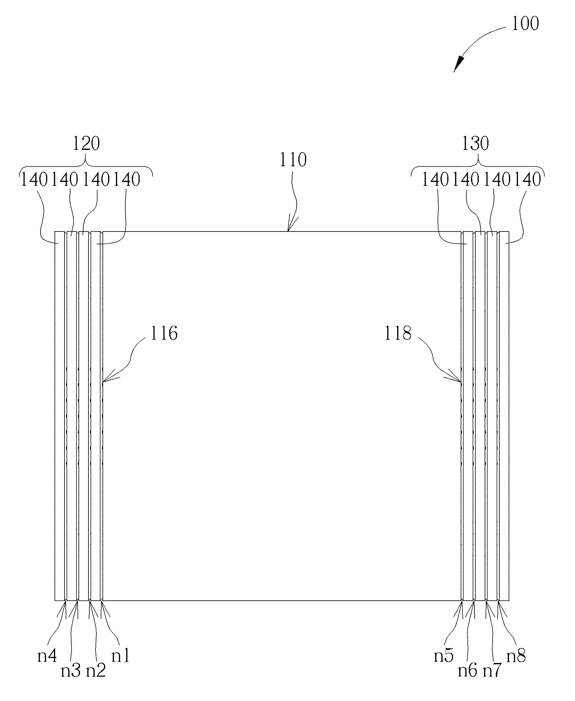
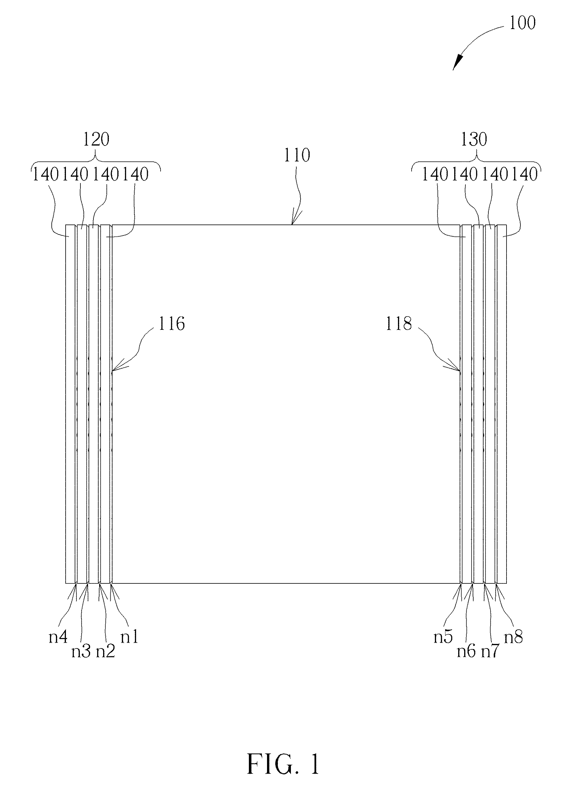
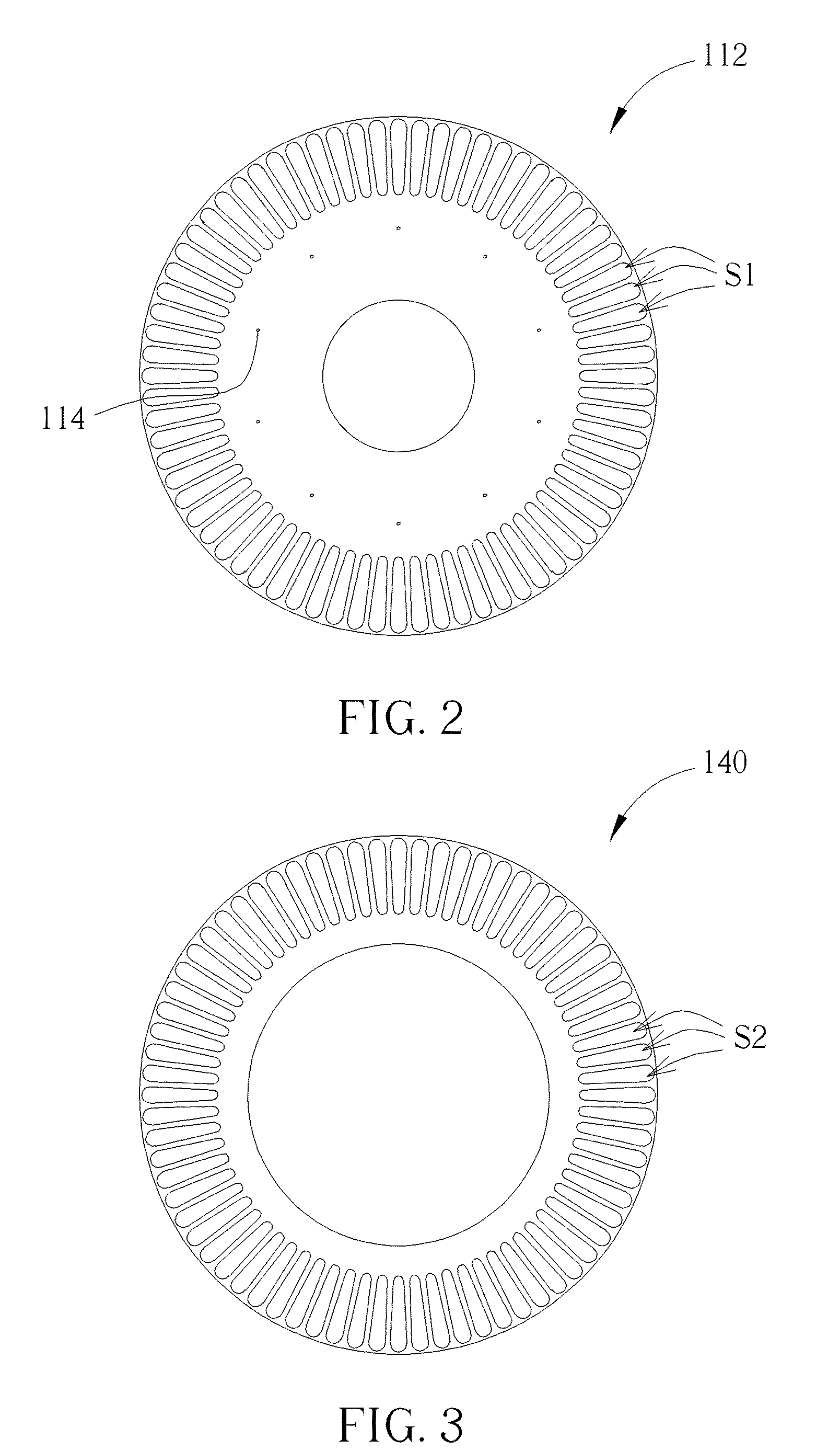
[0019]Please refer to FIG. 1 to FIG. 3. FIG. 1 is a diagram showing a rotor of an induction motor of the present invention. FIG. 2 is a diagram showing a core disc of a core assembly of the present invention. FIG. 3 is a diagram showing a conductive ring of an end ring assembly of the present invention. The rotor 100 of the induction motor of the present invention comprises a core assembly 110, a first end ring assembly 120, and a second end ring assembly 130. The core assembly 110 comprises a plurality of core discs 112 stacked on each other. The core discs 112 are mutually connected through the connecting points 114. For example, the core discs 112 can be riveted together through the connecting points 114. Each of the core discs 112 is formed with a plurality of slots S1. The core discs 112 of the core assembly 110 can be formed by stamping. Preferably, the core discs 112 can be made of steel.

[0020]The first end ring assembly 120 is adjacent to a first end surface 116 of the core ...


PUM

PropertyMeasurementUnit
depthaaaaaaaaaa
conductiveaaaaaaaaaa
areaaaaaaaaaaa

Abstract

A rotor of an induction motor includes a core assembly including a plurality of core discs formed with a plurality of slots; a plurality of conductive bars passing through the slots, each of the conductive bars having a first end and a second end respectively extended out of a first end surface and a second end surface of the core assembly; a first end ring assembly including a plurality of first conductive rings stacked on each other and penetrated by the first ends of the conductive bars; and a second end ring assembly including a plurality of second conductive rings stacked on each other and penetrated by the second ends of the conductive bars; wherein the first conductive rings and the second conductive rings are respectively welded to the first ends and the second ends of the conductive bars by electron beam welding or laser welding.

Description

BACKGROUND OF THE INVENTION[0001]1. Field of the Invention[0002]The present invention relates to a rotor of an induction motor, and more particularly, to a rotor of an induction motor with end ring assemblies formed by electron beam welding or laser welding.[0003]2. Description of the Prior Art[0004]A rotor of an induction motor generally comprises a shaft and a laminated magnetic core mounted to the shaft. The laminated magnetic core is formed with a plurality of slots for allowing a plurality of conductive bars to pass through. The conductive bars extend out of both ends of the laminated magnetic core, and an end ring or end cap at either end of the laminated magnetic core is configured to mechanically and electrically connect to the conductive bars.[0005]In one well known method of rotor production, the conductive bars and the end rings are integrally formed by casting. However, the conductive bars may shrink after formation, such that the conductive bars are loose in the slots. ...

Claims


Application Information

Patent Timeline
Patent Type & Authority Patents(United States)
IPC IPC(8): H02K17/00H02K15/00H02K17/16B23K15/00
CPCH02K17/165H02K15/0012B23K15/0046B23K26/21H02K1/28H02K15/02
Inventor CHEN, RUILIN RAYMA, JIFEI
Owner XPT NANJING E POWERTRAIN TECH CO LTD
Why Eureka
Try Eureka