Charger for hand-held power tool, power tool system and method of charging a power tool battery

a technology of power tool and charging system, which is applied in the direction of manufacturing tools, portable power tools, transportation and packaging, etc., can solve the problems of difficult or at least very inconvenient charging of the battery pack frequently during work intermissions, limited charging storage capacity of the battery pack, and limited work volume. , to achieve the effect of reducing the amount of work, and reducing the cost of battery pack charging

Active Publication Date: 2017-02-21
MAKITA CORP
View PDF105 Cites 15 Cited by
  • Summary
  • Abstract
  • Description
  • Claims
  • Application Information

AI Technical Summary

Benefits of technology

[0004]Cordless (i.e. battery-powered) power tools eliminate the need to connect the power tool to an external power supply (i.e. to a commercial AC power source) when a user is using the hand-held power tool (hereinbelow, simply called a “power tool”). The user need only charge the battery pack before using the power tool. However, the charge storage capacity of a battery pack is limited, and the amount of work that the power tool can perform depends on the charge storage capacity. Therefore, the charge storage capacity of the battery pack is preferably large in order to provide a long usage time before charging is required. However, if the charge storage capacity of the battery pack is increased, but the battery chemistry is not changed, the size, weight, etc. of the battery pack must also increase. That is, while increasing the charge storage capacity of the battery pack increases the amount of work that the power tool can perform, doing so also makes the power tool more difficult (heavy, bulky, expensive, etc.) for the user to use, which is a problem.

Problems solved by technology

However, the charge storage capacity of a battery pack is limited, and the amount of work that the power tool can perform depends on the charge storage capacity.
That is, while increasing the charge storage capacity of the battery pack increases the amount of work that the power tool can perform, doing so also makes the power tool more difficult (heavy, bulky, expensive, etc.) for the user to use, which is a problem.
However, in order to achieve such frequent (re-)charging using previously known charging techniques, the charger must always be located near the user, which would restrict the movement of the user of the power tool, because the charger must remain at a fixed location in order to connect to an AC power source.
Therefore, because known chargers for power tools must be plugged into an AC power source (which is usually fixed in location or is at least not conveniently movable), it would difficult or at least very inconvenient to charge the battery pack frequently during work intermissions (e.g., when moving locations or changing stances) using known chargers.

Method used


Image

  • Charger for hand-held power tool, power tool system and method of charging a power tool battery
  • Charger for hand-held power tool, power tool system and method of charging a power tool battery
  • Charger for hand-held power tool, power tool system and method of charging a power tool battery

Examples


first embodiment

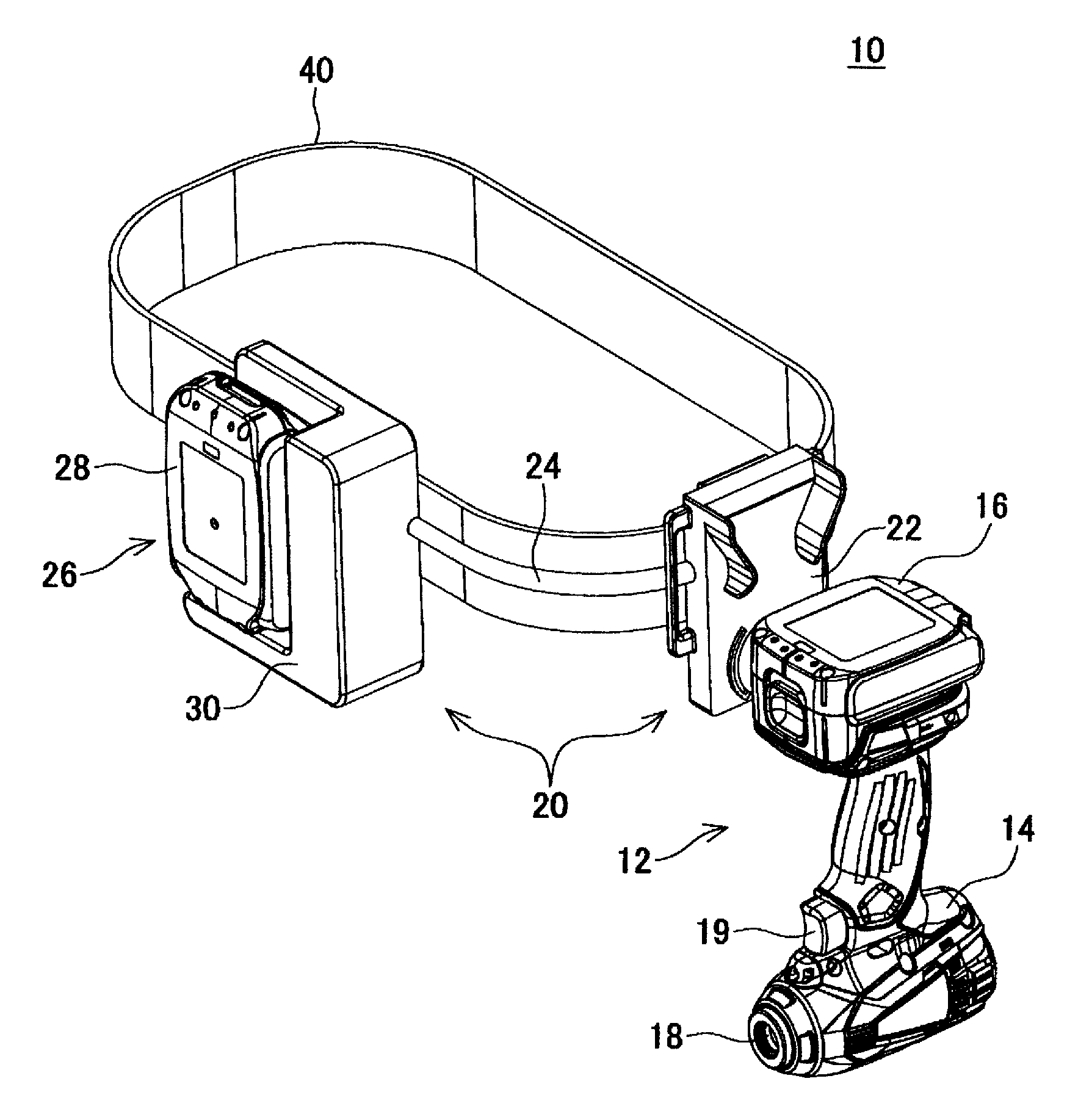
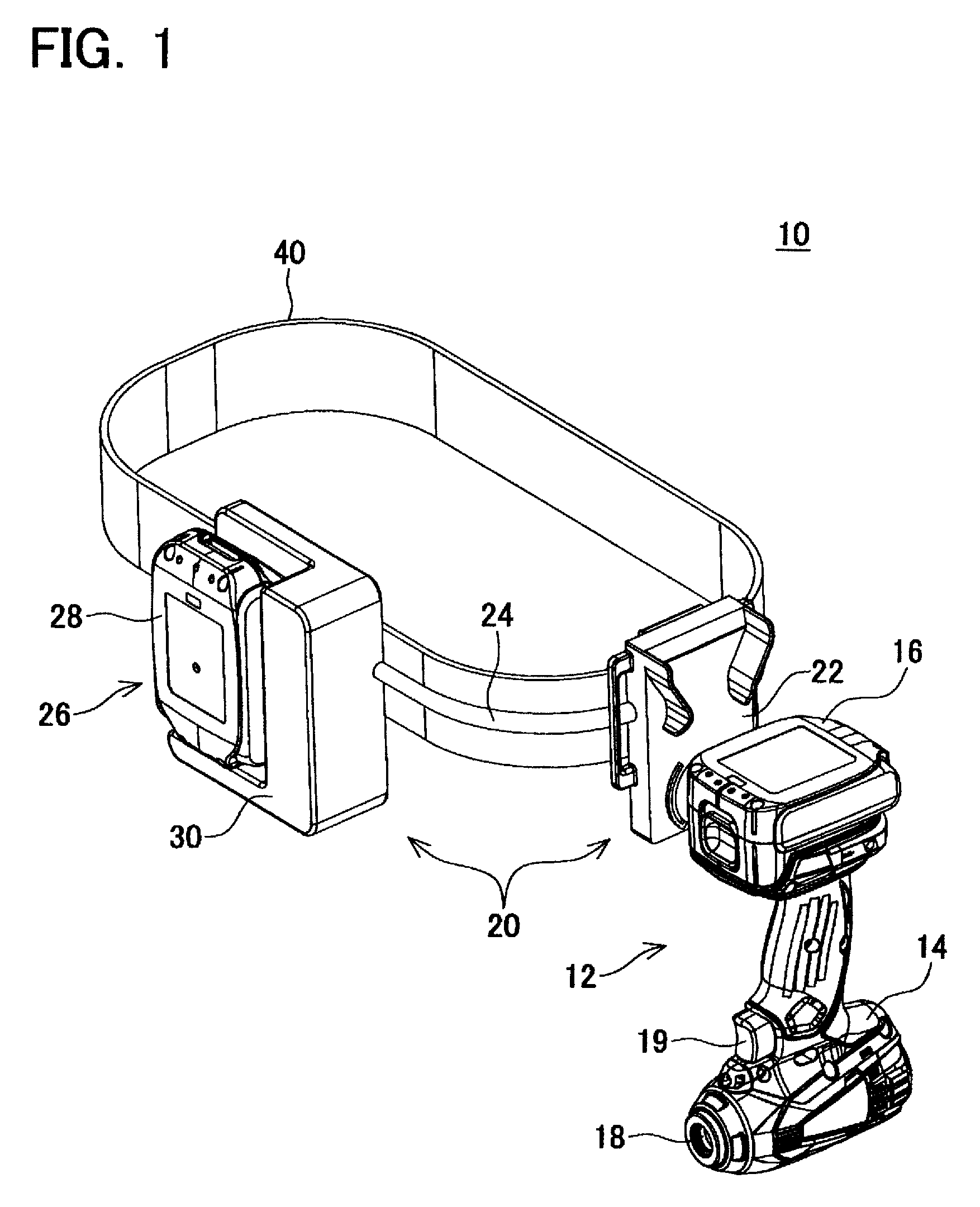
[0078]A power tool system 10 of a first embodiment will now be explained with reference to the drawings. As shown in FIG. 1, the power tool system 10 comprises a hand-held power tool 12 and a charger 20. The power tool 12 comprises a tool main body 14 and a first battery pack 16. The tool main body 14 has an internal motor, which rotationally drives a tool and a tool shaft or chuck 18. The first battery pack 16 has a plurality of internal secondary batteries (e.g., lithium-ion cells) and supplies the drive current to the motor in response to the user's operation of a trigger 19. In the present embodiment, the first battery pack 16 can be attached to and detached from the tool main body 14. However, in place of the attachable / detachable first battery pack 16, one or a plurality of secondary battery cells may be directly built into the tool main body 14.

[0079]The charger 20 comprises a charger main body (base) 22 and a battery power supply 26. The charger main body 22 and the battery ...

second embodiment

[0102]A power tool system of a second embodiment will now be explained with reference to FIG. 11. The system of the present embodiment differs from the system 10 of the first embodiment only in the structure of the charger main body 22. As shown in FIG. 11, the charger main body 22 of the present embodiment is specialized for right-handed users, and the holding member 62 can rotate in only one direction. Of course, it is also possible to implement a charger main body that is specialized for left-handed users by reversing, with bilateral symmetry, the structure of the charger main body 22 of the present embodiment.

third embodiment

[0103]A power tool system 210 of a third embodiment will now be explained with reference to FIGS. 12-20. The system 210 of the present embodiment differs from the system 10 of the first embodiment in that the system 210 comprises a charger main body (base) 222 and a charging adapter 270. The power tool 12 is not modified. In addition, although not shown, a battery power supply is connected to the charger main body 222 via an electrical cord. The circuit structure of the present embodiment is also substantially the same as that of the first embodiment. In particular, it is noted that the battery power supply may utilize the same second battery pack 28 as the first embodiment described above.

[0104]As shown in FIGS. 12A and 12B, in the system 210 of the present embodiment, the power tool 12, which has the charging adapter 270 attached thereto (discussed below), also can be attached to and detached from the charger main body 222. After being attached to the charger main body 222, the po...


PUM


Abstract

A charger for a hand-held power tool includes a power source interface, a charger base and a charging cradle rotatably supported on the charger base. The rotatable charging cradle includes at least two charging output terminals electrically connected to the power source interface. A power tool system includes the charger and the hand-held power tool. A method of charging the power tool system includes contacting charging input terminals of the power tool with the charging output terminals, rotating the charging cradle and the power tool relative to the charging base and supplying charging current to at least one battery cell while the charging cradle and the power tool are allowed to freely swing relative to the charging base.

Description

CROSS-REFERENCE[0001]This application is the U.S. National Stage of International Application No. PCT / JP2012 / 004605 filed on Jul. 19, 2012, which claims priority to U.S. provisional patent application No. 61 / 511,092 filed on Jul. 24, 2011, U.S. provisional patent application No. 61 / 581,950 filed on Dec. 30, 2011 and U.S. provisional patent application No. 61 / 664,928 filed on Jun. 27, 2012, the contents of which are incorporated herein by reference.TECHNICAL FIELD[0002]The present invention generally relates to a charger for a hand-held power tool system that utilizes a rechargeable battery as a power supply, to a power tool system that includes the charger, as well as to a method for charging the rechargeable battery using the charger.BACKGROUND ART[0003]A hand-held power tool (i.e. a cordless power tool) having a battery pack that serves as a power supply is disclosed in WO2006 / 044693A2. This power tool system comprises a hand-held power tool, which has the battery pack, and a char...

Claims


Application Information

Patent Timeline
Patent Type & Authority Patents(United States)
IPC IPC(8): H02J7/00
CPCH02J7/0042H02J7/0044H02J7/0054H02J7/342A41F9/002A45F3/14A45F2003/142A45F2003/144A45F2003/146B25F5/02
Inventor YOSHIKAWA, SHUJINAGAHAMA, TATSUYAFURUI, NOBUYASUSUZUKI, HITOSHIFUKUMOTO, MASAAKIUMEMURA, TAKUYAITO, KOSUKE
Owner MAKITA CORP
Why Eureka
Try Eureka