Built-in self-test technique for detection of imperfectly connected antenna in OFDM transceivers

a technology of transceivers and self-testing, which is applied in the direction of transmitter monitoring, orthogonal multiplex, instruments, etc., can solve the problems of low network coverage, low signal strength, and difficult detection even by end users

Inactive Publication Date: 2017-02-21
OPTIS CIRCUIT TECH LLC
View PDF18 Cites 0 Cited by
  • Summary
  • Abstract
  • Description
  • Claims
  • Application Information

AI Technical Summary

Benefits of technology

[0022]the clock of said OFDM communication transceiver is set faster than in normal operations, so as to increase the bandwidth of said signal at the output of said emitting chain;

Problems solved by technology

Badly connected antenna spring contact may cause a situation where the phone works somehow in locations where the mobile network's coverage is strong (big cities, etc.) and poorly in the country side or in any locations where the network's coverage is low (lower signal strength).
This situation is very hard to detect even by the end user.
The service center clerk will then not be able to notice any problems with the mobile phone (unless the antenna circuit is completely disconnected).
A measured input power below the transmitted value, or a measured frequency offset higher than a predetermined one means that the antenna circuit is not well connected.
However, these solutions are insufficient in detecting a defective antenna mechanical contact.

Method used


Image

  • Built-in self-test technique for detection of imperfectly connected antenna in OFDM transceivers
  • Built-in self-test technique for detection of imperfectly connected antenna in OFDM transceivers
  • Built-in self-test technique for detection of imperfectly connected antenna in OFDM transceivers

Examples


Embodiment Construction

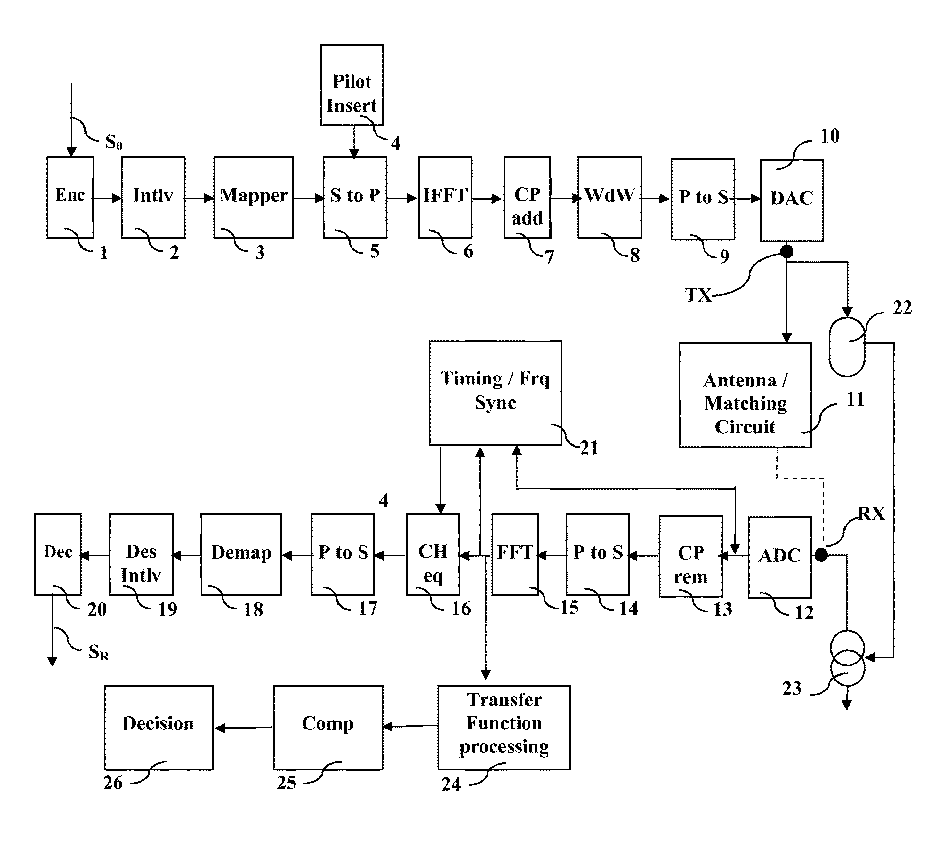
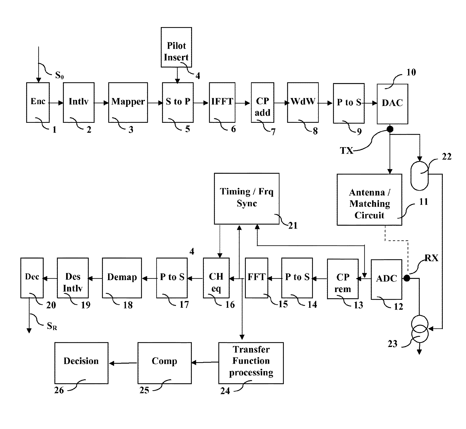
[0042]The invention consists in testing the presence (or good connection) of the antenna circuit from a different point of view than the existing techniques. The self-test is performed by measuring on-chip the quality factor and / or the resonance frequency of the antenna circuit, rather than testing the impedance, the frequency offset and / or the signal strength like the prior art solutions.

[0043]As it has been said, with non-soldered contacts, the impedance, the power etc. are not good criteria for checking the quality of the contact.

[0044]On the opposite, the applicant has considered that a defective antenna spring contact detunes the resonance of the antenna circuit and / or changes its quality factor.

[0045]In addition:[0046]Detuning the resonance of the antenna circuit causes a nonlinear gain in the bandwidth of the received and transmitted signals. Under certain conditions (poor network), this drives the circuit to a faulty behavior without changing the overall gain of the signal.[...


PUM


Abstract

An OFDM communication transceiver, which is configured to test its connection with an antenna circuit unit, has a receiver chain and an emitting chain. The receiver chain includes a time-to-frequency transform unit and the emitting chain includes a frequency-to-time transform unit. The transceiver further includes means for disconnecting the receiver chain to the antenna circuit unit, means for providing a stimulus as input to the emitting chain, means for reintroducing the signal at the output of the emitting chain as an input of the receiving chain, means for determining a circuit resonance frequency, Fr, and a quality factor, Q, of a transfer function computed from the output of the time-to-frequency transform unit, and means for deciding about the connection of said antenna circuit unit according to the resonance frequency and the quality factor.

Description

FIELD OF THE INVENTION[0001]The invention relates to the field of self-test of antennas in wireless communication systems and more particularly in multicarrier communication systems like Orthogonal Frequency-Division Multiplexing (OFDM) systems.BACKGROUND OF THE INVENTION[0002]Due to manufacturing needs, mobile phone manufacturers use mechanical structure where the antenna circuit (i.e. the physical antenna and its matching and filtering circuits) is connected to the phone handset with spring contacts, instead of soldering for instance.[0003]Badly connected antenna spring contact may cause a situation where the phone works somehow in locations where the mobile network's coverage is strong (big cities, etc.) and poorly in the country side or in any locations where the network's coverage is low (lower signal strength).[0004]This situation is very hard to detect even by the end user. Plus, even in the case where the end user detects a bad behavior of his or her mobile phone handset, s / ...

Claims


Application Information

Patent Timeline
Patent Type & Authority Patents(United States)
IPC IPC(8): H04B3/00H04B17/15H04B17/19H04J4/00H04L7/02H04J11/00H04B17/14H04B7/216H04B17/17H04B17/18G01R31/3187
CPCH04B17/19H04B17/14H04B17/15H04J4/005H04J11/00H04L7/02G01R31/3187H04B17/17H04B17/18
Inventor DHAYNI, ACHRAF
Owner OPTIS CIRCUIT TECH LLC
Why Eureka
Try Eureka