Heat dissipating device

a heat dissipating device and heat dissipation technology, applied in semiconductor devices, semiconductor/solid-state device details, cooling/ventilation/heating modifications, etc., can solve the problems of affecting operating efficiency, vapor chambers are prone to deformation, and electronic components generate more and more heat. , to achieve the effect of enhancing the structural stability of the heat dissipating devi

Active Publication Date: 2017-02-21
CHAUN CHOUNG TECH
View PDF9 Cites 4 Cited by
  • Summary
  • Abstract
  • Description
  • Claims
  • Application Information

AI Technical Summary

Benefits of technology

[0014]Fourth, a separating space is formed between any two adjacent legs. The separating space receives an extending portion extending from the fin set. The extending portion is engaged with the corresponding two adjacent legs. In this way, the fin set is positioned by the fixture to enhance the structural stability of the heat dissipating device.

Problems solved by technology

As a result, the electronic components generate more and more heat.
However, if the electronic components keep operating at a high temperature, the operating efficiencies will be affected.
However, the above traditional heat dissipating device has the following disadvantages.
Because the vapor chamber has a plate shape, the vapor chamber is prone to deform from the point of pressure concentration when being pressed.
Consequently, the vapor chamber cannot be attached smoothly to the electronic component, which further reduces the heat dissipation efficiency of the heat dissipating device.

Method used


Image

  • Heat dissipating device
  • Heat dissipating device
  • Heat dissipating device

Examples


Embodiment Construction

[0020]As for the characteristics and technical details of the present invention, please refer to the following detailed description and accompanying figures. However, the accompanying figures are only for reference and explanation, but not to limit the scope of the present invention.

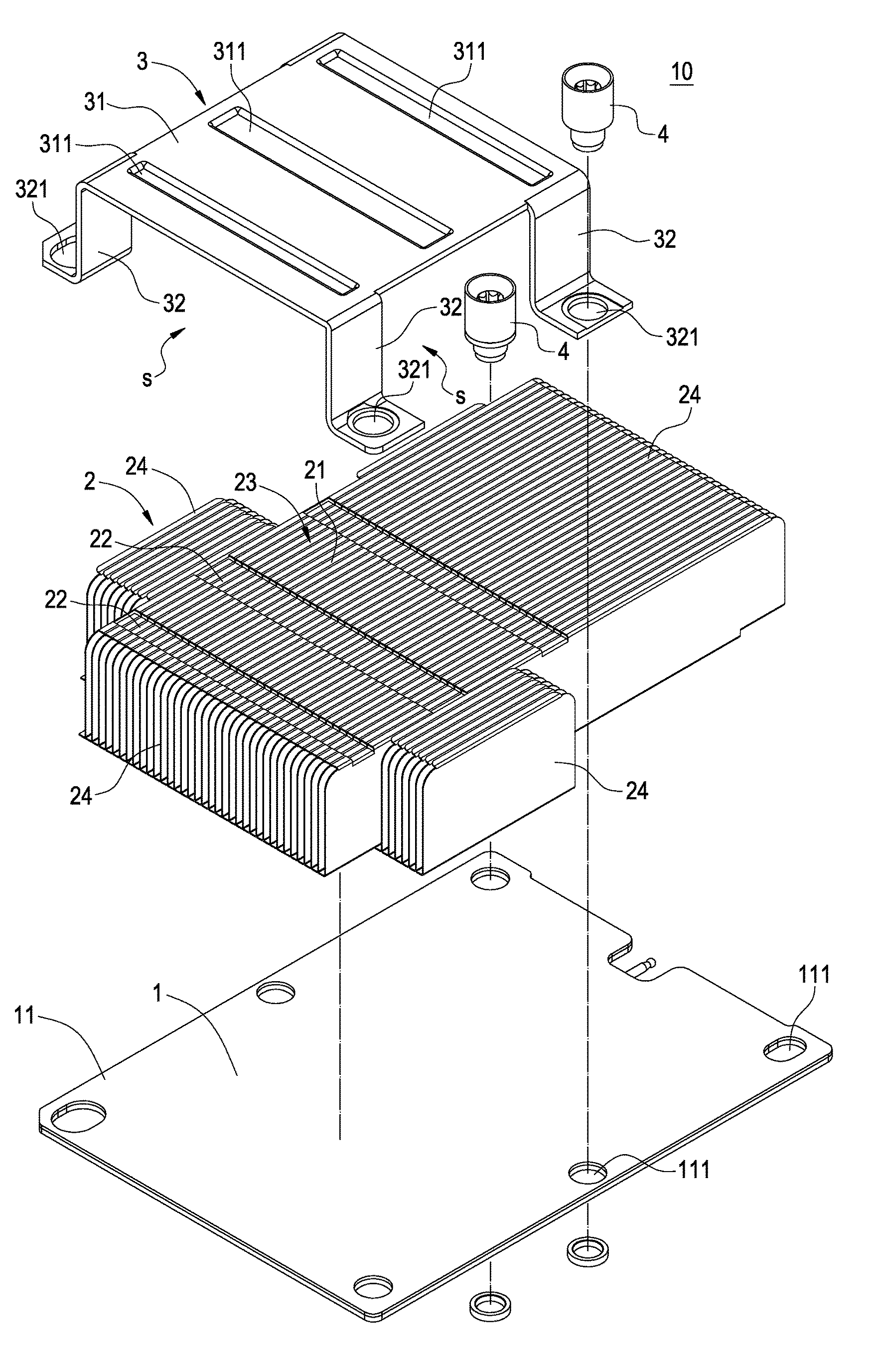
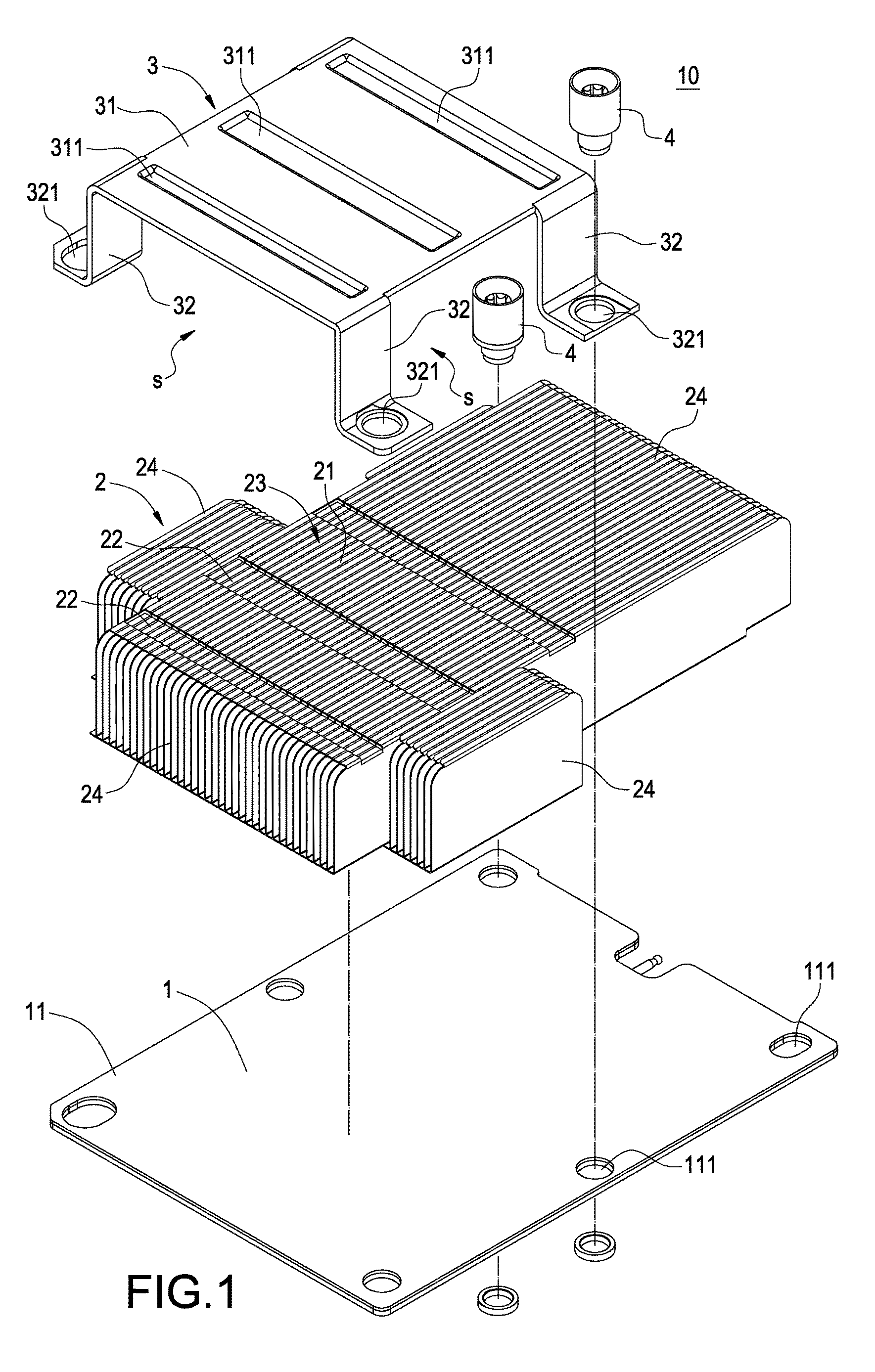
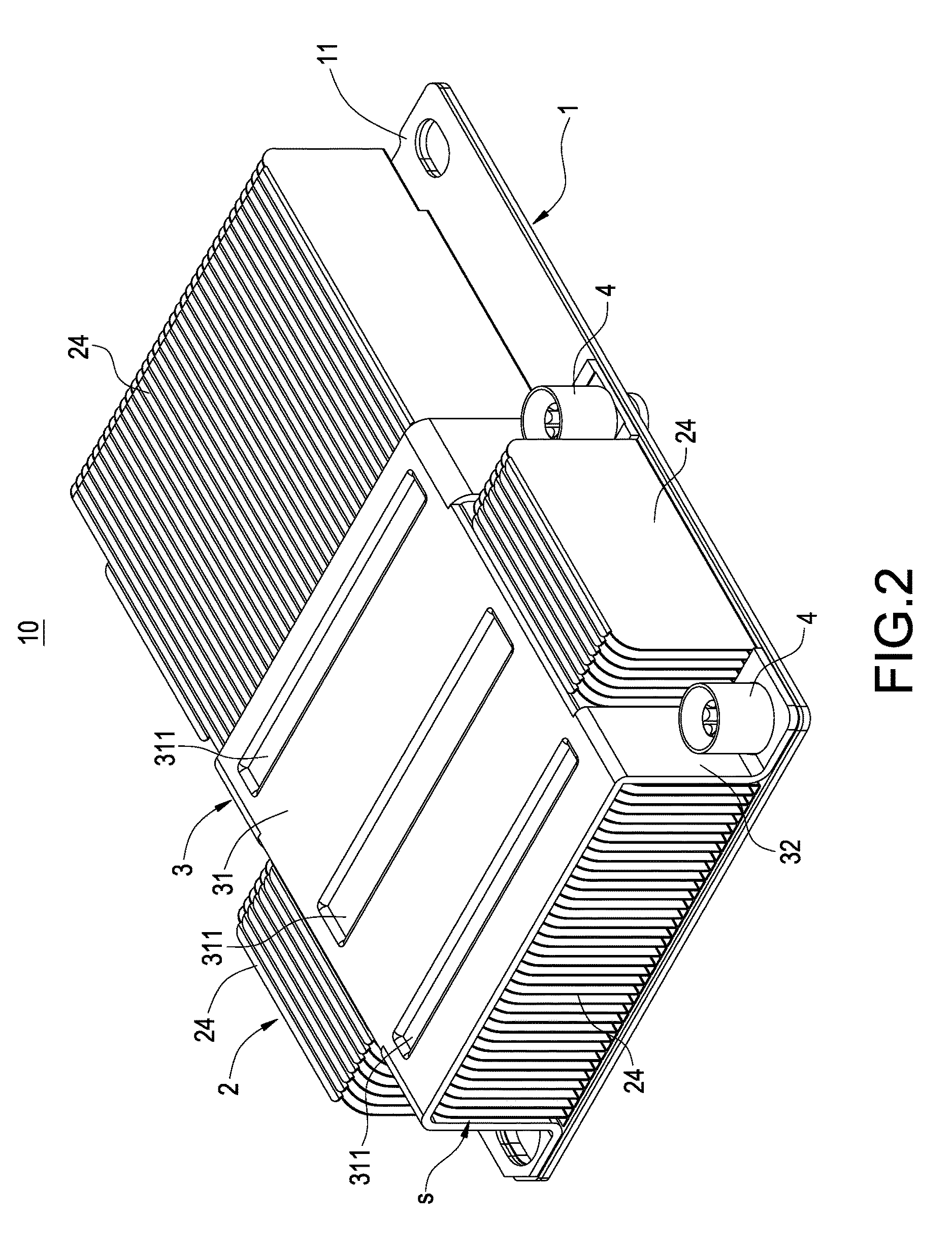
[0021]Please refer to FIGS. 1-5. The present invention provides a heat dissipating device 10 which comprises a vapor chamber 1, a fin set 2, and a fixture 3.

[0022]As shown in FIG. 5, the heat dissipating device 10 is used for a PCB 100. The PCB 100 has a heat generating component 200. The PCB 100 is provided with a plurality of first fixing holes 101.

[0023]As shown in FIGS. 1-5, the vapor chamber 1 is attached to the heat generating component 200. An end plate 11 is extended from an external edge of the vapor chamber 1 and provided with a plurality of throughholes 111.

[0024]As shown in FIGS. 1-5, the fin set 2 is connected above to the vapor chamber 1. A plurality of recess slots 22 are disposed at the t...


PUM


Abstract

A heat dissipating device used for a PCB having a heat generating component includes a vapor chamber, a fin set, and a fixture. The vapor chamber is attached to the heat generating component. The fin set is connected above to the vapor chamber. The fixture is fixed to the PCB. The vapor chamber and the fin set are clamped between the fixture and the PCB. The fixture has a press plate which is pressed against a top of the fin set. Therefore, the press plate presses the vapor chamber without direct contact. That is, the applied pressure is concentrated on the fin set and then distributed evenly to the vapor chamber, which prevents deformation of the vapor chamber due to uneven pressure and further achieves the effect of the vapor chamber being attached smoothly to the heat generating component.

Description

BACKGROUND OF THE INVENTION[0001]Field of the Invention[0002]The present invention relates to a heat dissipating device, in particular, to a heat dissipating device which is used to dissipate the heat generated by the electronic components.[0003]Description of Related Art[0004]With the prevailing application of 3C products by people, the operating speed and performance of the electronic components such as the CPUs in the 3C products are required to be improved constantly. As a result, the electronic components generate more and more heat. However, if the electronic components keep operating at a high temperature, the operating efficiencies will be affected. Thus, a heat dissipating device is usually used by the industry to facilitate the cooling of the electronic components.[0005]A vapor chamber uses the circulation mechanism of evaporation and condensation of a working fluid sealed in a plate-shaped chamber, which can make the heat generated by the electronic components be dissipat...

Claims


Application Information

Patent Timeline
Patent Type & Authority Patents(United States)
IPC IPC(8): H01L23/367H05K7/20H01L23/473H01L23/427H01L23/467
CPCH05K7/20309H05K7/20318H01L23/367H01L23/427H01L23/473H01L23/3677H01L23/467H01L23/46
Inventor SHIH, PO-CHOUHSU, HENG-CHICHEN, TUN-TA
Owner CHAUN CHOUNG TECH
Why Eureka
Try Eureka