
Method of controlling a lighting system

a lighting system and control command technology, applied in the field of lighting system control, can solve the problems of different delays in the reception of different control commands for different light source nodes, different delays, and unpleasant visual impression of the state-shift, such as wake-up or switch off lights, and achieve the effect of improving the visual effect of the state-shi

Inactive Publication Date: 2017-02-28
SIGNIFY HLDG BV
View PDF18 Cites 0 Cited by
  • Summary
  • Abstract
  • Description
  • Claims
  • Application Information

AI Technical Summary

Benefits of technology

[0007]The present invention is based on the understanding that each node in the network for example may be synchronized based on a time synchronization of the plurality of nodes. In summary, said time synchronization provides the plurality of operating nodes with a common notion of time, thereby allowing for task synchronization, such as for example light sources controlled by the operating nodes. Other devices, units, and so on, that are controllable by the operating nodes are of course also possible. That is to say, synchronizing the execution of specific tasks performed by nodes in a network is possible. Time synchronization, i.e. time alignment between two nodes, may for example be achieved by estimating a time offset between two nodes, and providing an estimate of the difference in progress rate between two clock mechanisms belonging to the two nodes, respectively. The difference in counting rate is used to keep a good estimate of the current time of the other node.
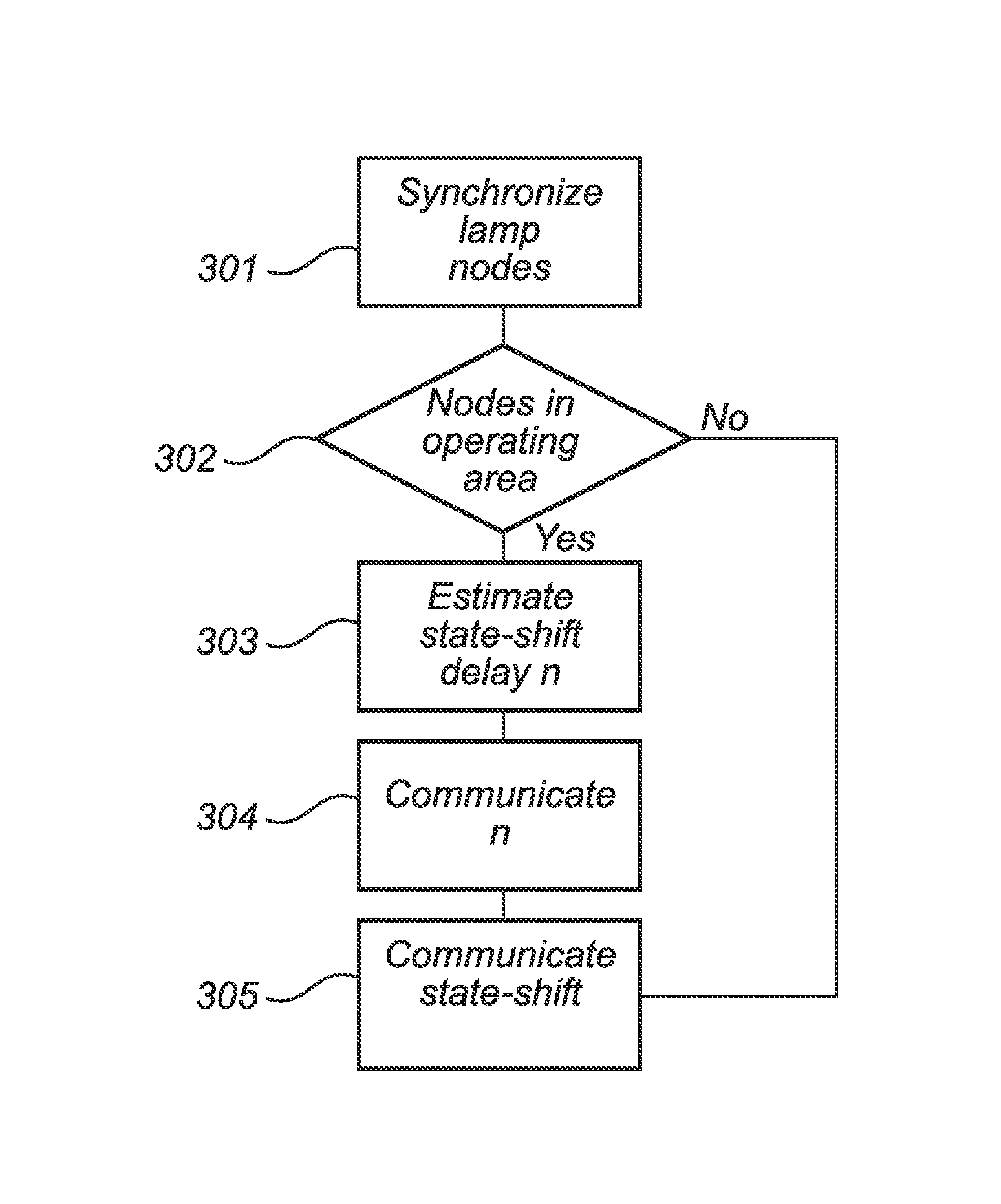
[0013]An advantage with the invention is that for example a visual impression of the state-shift (when for example light sources are controlled operating nodes) may be essentially eliminated as the time synchronization and timer interrupt alignment together with the estimated state-shift delay allows the plurality of nodes, or at least the set of nodes within the predetermined operating area, to shift state at essentially the same time. A further advantage with the invention is that the essentially simultaneous state-shift will reduce the sometimes audible effect in such a lighting system. It should be noted that in view of the multiplicity of controllers, the controllers may be synchronized to each other or to already synchronized nodes in the network.
[0016]Moreover, the state-shift delay may be at least one of a state transition time for each operating node (e.g. from OFF to ON), and a maximum communication delay between the controller and the set of operating nodes located within the predetermined operating area. Also, the state-shift command may comprise an operation node-specific variable for creating a predetermined state-shift pattern. This would allow for the introduction of predetermined visual patterns when for example switching ON and OFF the light sources.
[0021]The state-shift may be a request for “wake up” (e.g. switching ON) or switch OFF of a light source connected to the operation node, wherein the visual effect of light sources waking up or switching OFF may be synchronized. This may be advantageous, since a user of the system may experience a simultaneous wake up, or switch OFF, of all visible light sources, in contrast to the light sources waking up at different times, creating a so-called popcorn effect.
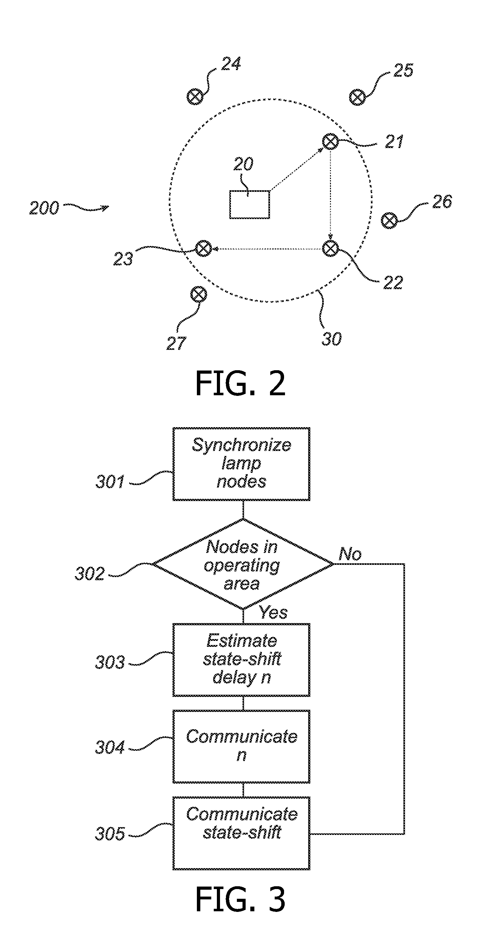
[0024]Furthermore, at least the set of operating nodes located within the predetermined operating area may be adapted to take into account the state-shift delay when executing the state-shift command. The operating nodes outside the predetermined area may hence execute the state-shift command when (or alternatively after) it is received. The visual effect of the state-shift may thereby be improved. For example, each light source within the predetermined operating area, such as a room visible to the user who switches on the lighting system, may wake up with an acceptable delay from the time the user switched on the system, whereas the remote light sources, outside the operating area, wake up in an asynchronous manner not noticeable by the user.

Problems solved by technology

However, in large-scale wireless lighting systems not all light source nodes may be in communication range with the lighting system controller.
Rather, large-scale lighting systems require state-shift commands from the controller to the light source nodes to be routed also between the different light source nodes, effectively introducing different control command reception delays for the different light source nodes.
Due to the nature of the different reception delays, the visual impression of the state-shift, such as wake-up or switch OFF lights, is unpleasant in that not all light source nodes shift state at the same time.
Besides, collisions, different routes or different nodes with different processing power may cause some different delays.

Method used


Image

  • Method of controlling a lighting system
  • Method of controlling a lighting system
  • Method of controlling a lighting system

Examples


Embodiment Construction

[0032]The present invention will now be described more fully hereinafter with reference to the accompanying drawings, in which currently preferred embodiments of the invention are shown. This invention may, however, be embodied in many different forms and should not be construed as limited to the embodiments set forth herein; rather, these embodiments are provided for thoroughness and completeness, and fully convey the scope of the invention to those skilled in the art. Like reference characters refer to like elements throughout.

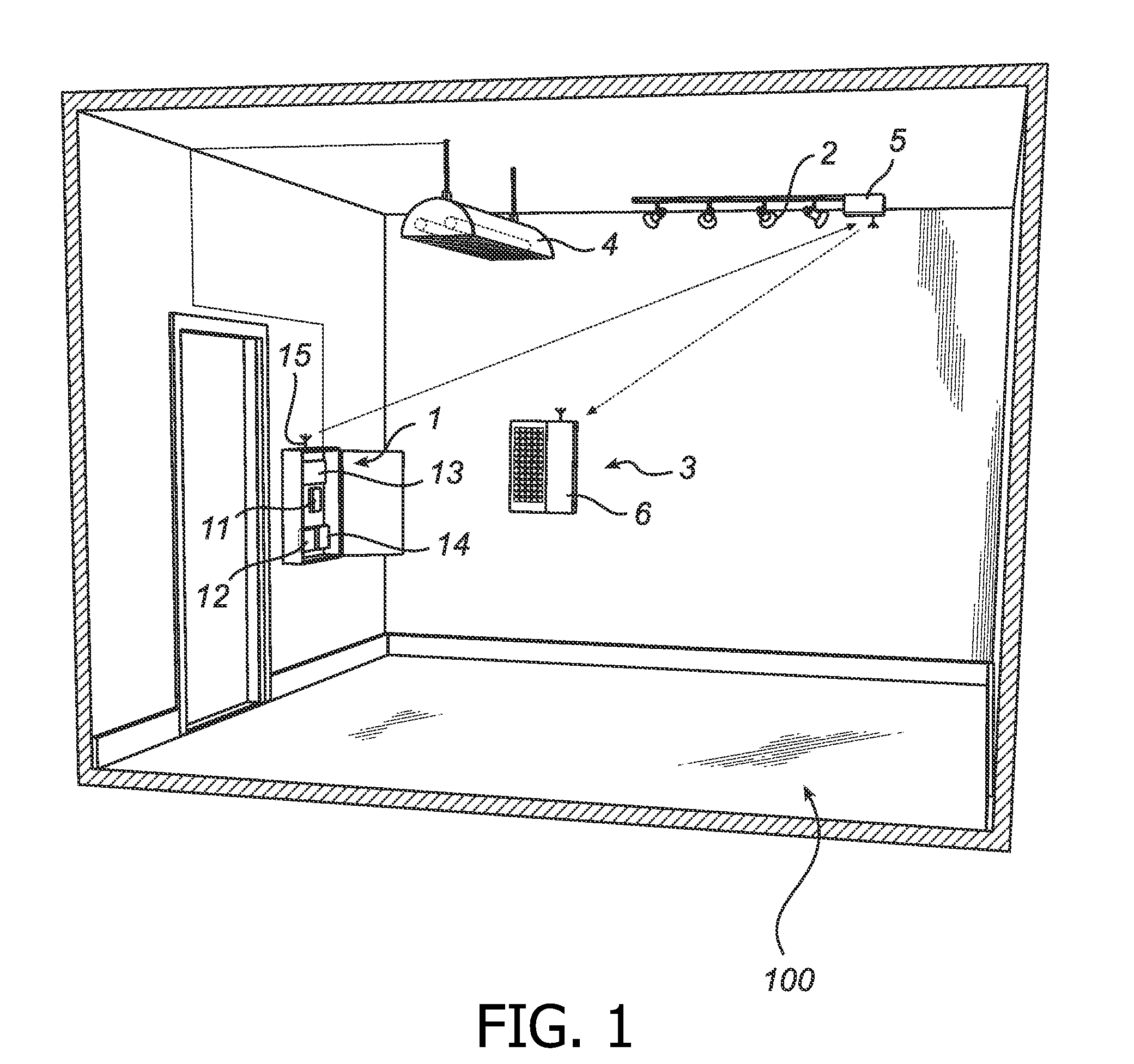
[0033]Referring now to the drawings and to FIG. 1 in particular, a lighting system 100 is depicted illustrating an exemplifying system in which the method of the present invention may be performed. The lighting system 100 comprises a controller 1 and a plurality of light source nodes 2, 3, 4 coupled together to form a network. For simplicity of explanation, there are only one controller 1 and three operating nodes 2, 3, 4, in the lighting system 100. Here, t...


PUM


Abstract

The present invention relates to a method of controlling a lighting system, the lighting system being arranged as a wireless network comprising a controller and a plurality of operating nodes arranged to communicate with each other, wherein the method comprises the steps of synchronizing the operating nodes with the controller, determining, from the plurality of operating nodes, a set of operating nodes that are located within a predetermined operating area, estimating a state-shift delay based on a maximum communication delay between the controller and the set of operating nodes located within the predetermined operating area, communicating the estimated state-shift delay to the plurality of operating nodes, and communicating a state-shift command to the plurality of operating nodes.An advantage with the invention is that the visual artifact of the state-shift may be essentially removed as the time synchronization and timer interrupt alignment together with the estimated state-shift delay allows for the plurality of nodes to shift state at essentially the same time.

Description

TECHNICAL FIELD[0001]The present invention relates to a method of controlling a lighting system. The invention also relates to a lighting system adapted for performing such a method.BACKGROUND OF THE INVENTION[0002]Wireless control of lighting systems is increasingly replacing wired control, for example reducing installation costs and commissioning effort. A number of wireless technologies have been developed, including for example IEEE-802.15.4, Low-Power WiFi, WiFi, Bluetooth, EnOcean, Z-Wave and similar technologies, which typically permit short range communication.[0003]For real-time control of a wireless lighting system, it is desired to minimize the latency when switching a state of the light source nodes of the lighting system. An example of such a lighting system is disclosed in US2006 / 0154598, where a group of light source nodes of a radio network are arranged to selectively respond to broadcast messages from a lighting system controller, thereby providing decreased latency...

Claims


Application Information

Patent Timeline
Patent Type & Authority Patents(United States)
IPC IPC(8): H05B37/02
CPCH05B37/0245H05B37/0281Y02B20/42H05B47/16H05B47/175Y02B20/40
Inventor SCHOOFS, ANTHONY ROBERT ANDREFUHRMANN, PETERAOUN, MARC
Owner SIGNIFY HLDG BV
Learn More