Methods and systems for hybrid vehicle waste heat recovery

a hybrid vehicle and waste heat recovery technology, applied in the direction of machines/engines, mechanical equipment, transportation and packaging, etc., can solve the problems of engine emissions and fuel economy depletion, not always beneficial to extract heat from the engine to produce electricity, and engine heat extraction may not be desirable, so as to improve engine fuel economy and emissions, improve engine warm-up, and generate electricity

Inactive Publication Date: 2017-03-07
FORD GLOBAL TECH LLC
View PDF22 Cites 13 Cited by
  • Summary
  • Abstract
  • Description
  • Claims
  • Application Information

AI Technical Summary

Benefits of technology

[0004]By extracting engine exhaust gas heat, it may be possible to both generate electricity and improve engine warm-up so as to improve engine fuel economy and emissions. In particular, heat extracted from engine exhaust may be routed to an expander and / or to an engine heat exchanger where engine exhaust heat may be transferred to engine coolant to heat the engine. The warmed engine coolant may allow the engine to reach a desired engine operating temperature in a shortened period of time, thereby reducing engine emissions and improving fuel economy. In one example, a bypass valve may be selectively operated to route a heat transfer medium or working fluid to either or both of an expander and an engine coolant heat exchanger. In this way, it may be possible to improve the functionality of an exhaust gas heat recovery system.
[0005]The present description may provide several advantages. In particular, the approach may improve engine starting emissions and fuel economy by reducing engine warm-up time. Further, the approach may extract engine heat from several locations so that less engine exhaust gas heat may be necessary to operate an expander that rotates a generator. Further still, the approach may provide heat to a vehicle cabin sooner than systems that rely solely on heat from an engine block to provide cabin heat.

Problems solved by technology

However, it may not always be beneficial to extract heat from the engine to produce electricity.
For example, it may not be desirable to extract heat from the engine when the engine is being started from cold conditions because engine emissions and fuel economy may degrade.
Consequently, the system may not be operated, or if the system is operated during cold engine conditions, it may not provide a desired output.

Method used


Image

  • Methods and systems for hybrid vehicle waste heat recovery
  • Methods and systems for hybrid vehicle waste heat recovery
  • Methods and systems for hybrid vehicle waste heat recovery

Examples


Embodiment Construction

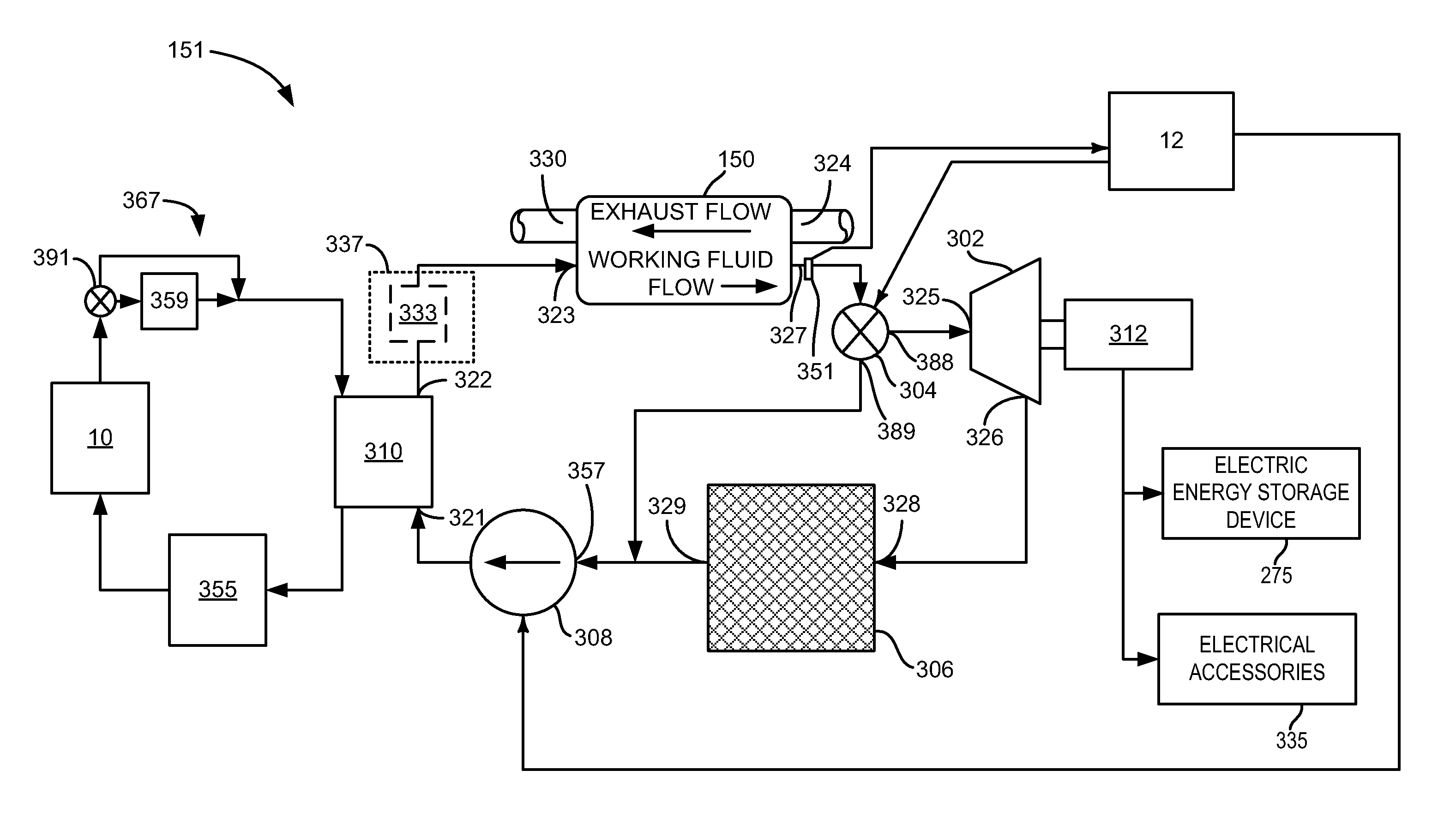
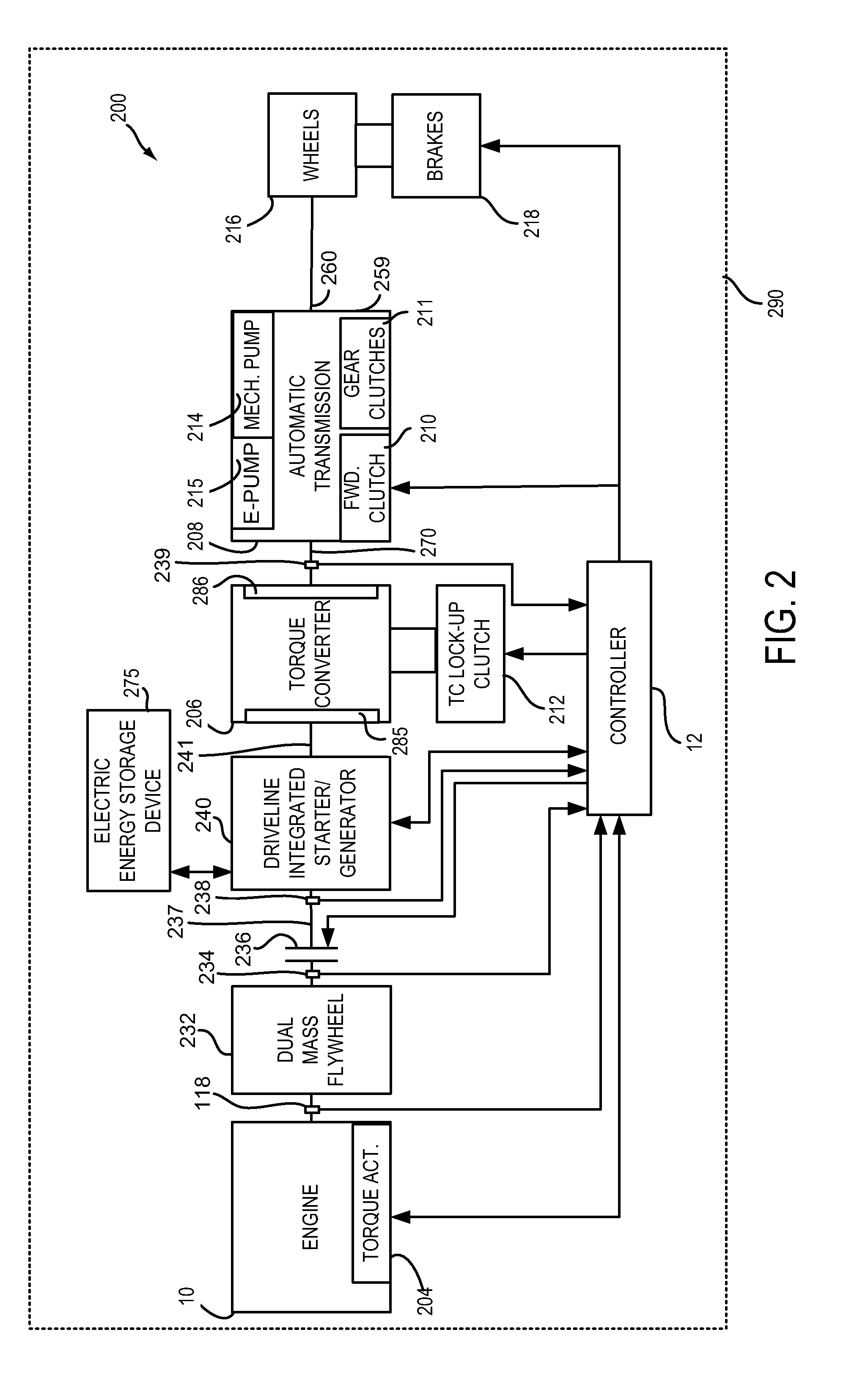
[0014]The present description is related to recovering energy from engine exhaust gases and using the recovered energy to improve vehicle operation. Exhaust gas energy may be recovered from an engine of the type described in FIG. 1, or a diesel engine. The engine may be part of a hybrid vehicle as is shown in FIG. 2. Energy may be extracted from engine exhaust gases via an exhaust gas energy recovery system as is shown in FIG. 3. The exhaust gas energy recovery system may be operated according to the method described by the flowchart shown in FIG. 4. The engine and exhaust gas heat recovery system may be operated in a sequence as shown in the sequence of FIG. 5.

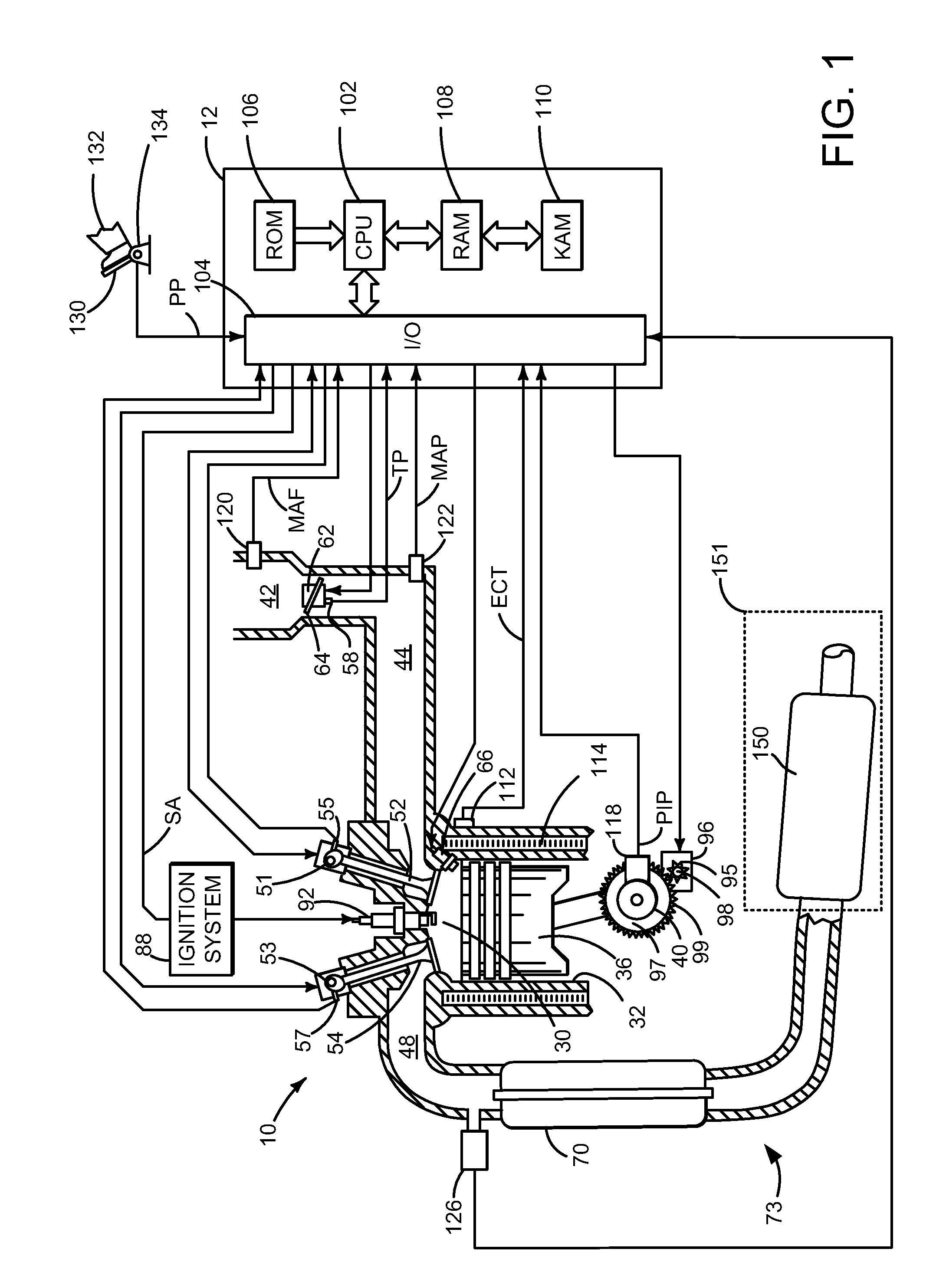
[0015]Referring to FIG. 1, internal combustion engine 10, comprising a plurality of cylinders, one cylinder of which is shown in FIG. 1, is controlled by electronic engine controller 12. Engine 10 includes combustion chamber 30 and cylinder walls 32 with piston 36 positioned therein and connected to crankshaft 40. Flywheel 97...


PUM


Abstract

Systems and methods for operating an engine that includes an exhaust gas heat recovery system are described. The system may selectively or contemporaneously supply energy from engine exhaust gas to generate electricity or warm the engine. In one example, exhaust gas energy raises a temperature of a heat transfer medium and the heat transfer medium is routed to an engine coolant heat exchanger or an expander via a bypass valve.

Description

FIELD[0001]The present description relates to a system and method for recovering waste heat of a hybrid vehicle. The system and methods described herein provide for recovering heat from exhaust gases to reduce engine warm-up time and generate electrical power.BACKGROUND AND SUMMARY[0002]An internal combustion engine converts a portion of chemical energy in a fuel into rotational energy and heat. A portion of heat energy generated by the engine may be regarded as waste heat energy. U.S. Pat. No. 7,353,661 describes a system where engine heat is extracted from engine coolant or exhaust gases to power a generator. A same refrigerant that is used to generate electricity is also used to cool a cabin of a vehicle. The electricity produced from engine heat may be stored in a battery or used within the vehicle. However, it may not always be beneficial to extract heat from the engine to produce electricity. For example, it may not be desirable to extract heat from the engine when the engine ...

Claims


Application Information

Patent Timeline
Patent Type & Authority Patents(United States)
IPC IPC(8): F01N5/02F02G5/04
CPCF01N5/02F02G5/04Y02T10/16Y02T10/166Y10S903/905Y02T10/12
Inventor HUSSAIN, QUAZI EHTESHAMBRIGHAM, DAVID RICHENSJENNINGS, MARK JOHN
Owner FORD GLOBAL TECH LLC
Why Eureka
Try Eureka