Fly-fishing float or strike indicator and attachment methods

Active Publication Date: 2017-03-14
SCHOENIKE LARRY
View PDF183 Cites 4 Cited by
  • Summary
  • Abstract
  • Description
  • Claims
  • Application Information

AI Technical Summary

Benefits of technology

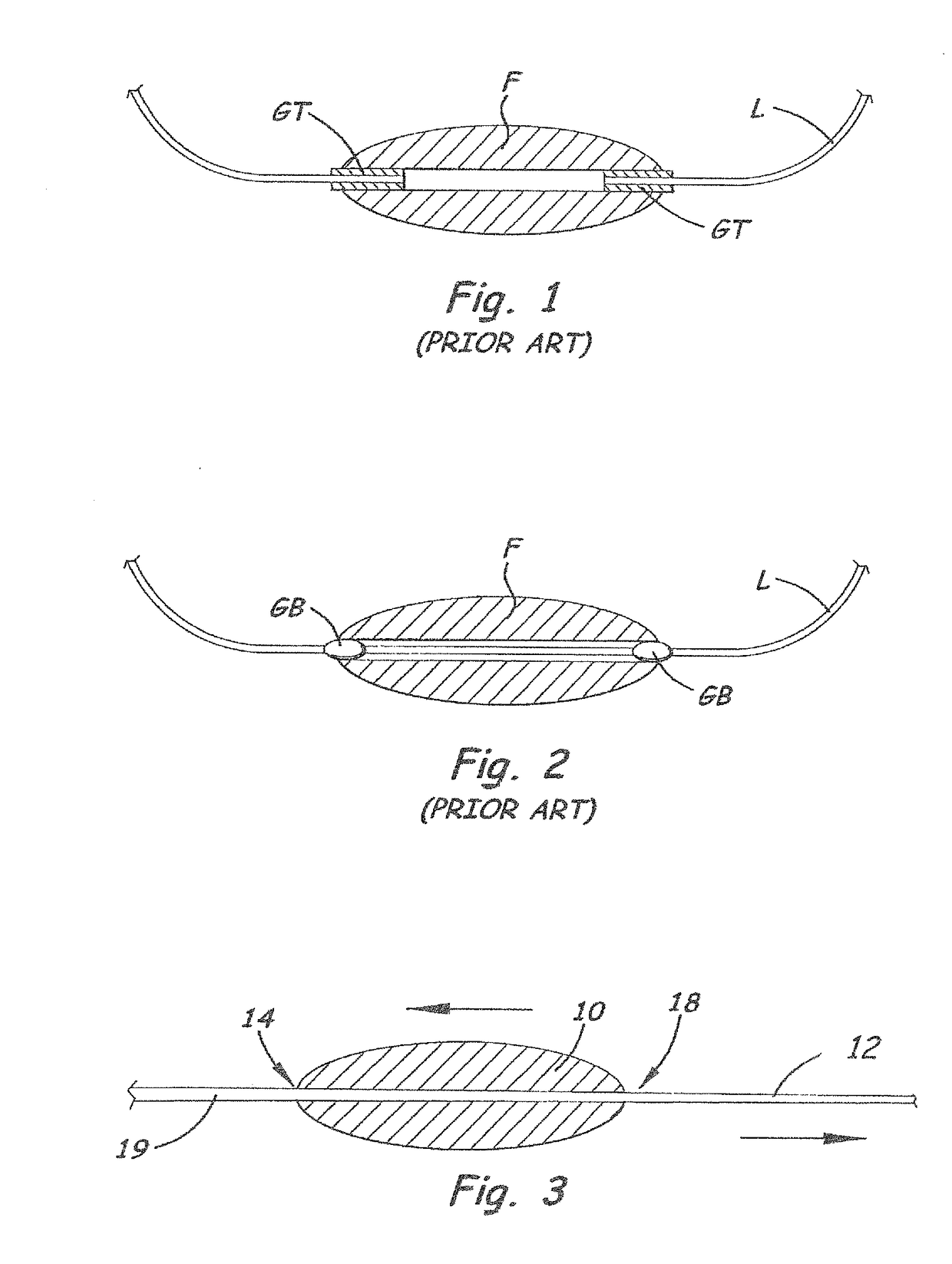
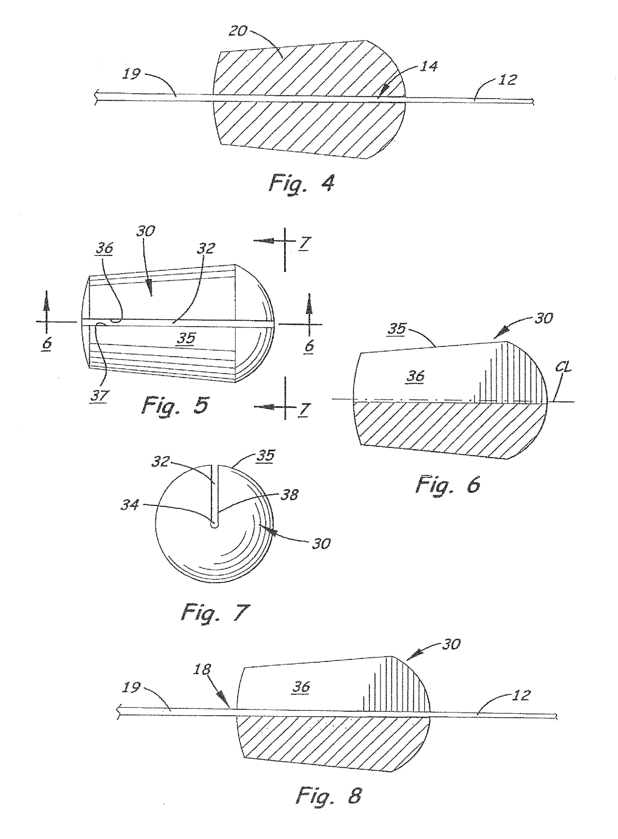
[0009]The present invention comprises embodiments of a float, and methods for attaching the floats, which comprise friction-fit or interference-fit of the float directly to the leader / line. In fly fishing applications, the float will often serve as a strike indicator as it floats downstream ahead of, or near, the fly. Upon a fish-strike, the float will be jerked or otherwise moved suddenly, signaling the fisherman that a fish-strike has occurred. In especially-preferred embodiments, the float may include a bore formed / defined substantially or entirely by a surface(s) that is less compressible than the leader that provides said friction-fit or interference-fit between the leader / line and the surface of the bore. An optional slot may be provided from the outer surface of the float to the bore, to aid in installation of the float especially on leaders that comprise a knot.
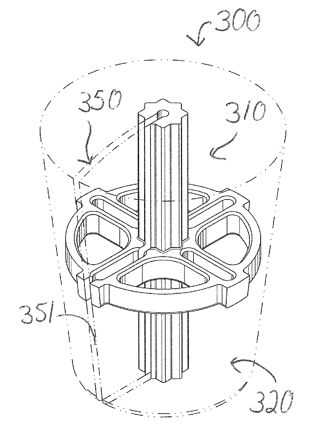
[0013]The non-compressible surface that defines the bore allows the float to be pushed toward the larger-diameter portion of a tapered leader, to a point wherein the leader is very tightly received in the bore. The bore surface is specially-adapted, by virtue of its non-compressibility, to firmly engage the leader without compressing or changing the bore surface shape or diameter, even when the float is pushed with substantial force onto said larger-diameter portion of the leader. The leader is more compressible than the insert, so that the force of “wedging” or “shoving” the leader into the non-compressible bore in a very tight fit results in at least a portion of the leader being compressed inside the bore. Thus, this compression of the leader, and the resulting tight interference fit, prevents the float from loosening or sliding relative to the leader, after installation, during casting, and during fishing, even though there are no grommets or other fasteners used. The inventor has found that the combination of the non-compressible insert surrounded by a very low-density material results in a float with superior performance, in terms of simple and extremely reliable installation on a fly-fishing leader, and excellent casting and strike-indication performance. The inventor has found that the non-compressible bore is less likely to become loosened on the leader than a compressible bore, for example, a bore formed and defined by a closed-cell polymeric foam surface.
[0014]In a first set of embodiments, the float is attached to a fly fishing leader by the leader being inserted longitudinally through the float bore, and pushed toward the larger-diameter leader end, until the very tight friction and / or interference fit is achieved. The float typically will not slide along the leader unless purposely slid relative to the leader by the fisherman or other person. In a second set of embodiments, the float is inserted through a side-slot in the float, to reach the longitudinal bore, after which float is pushed toward the larger-diameter portion of the leader, to create said very tight friction or interference fit.

Problems solved by technology

Such a float and gripper assembly is a “one-use” assembly, which is not removable and reusable on a different leader.
The fairly complex installation method recommended for this apparatus results in the two grippers gripping the leader tightly and also gripping the float tightly.

Method used


Image

  • Fly-fishing float or strike indicator and attachment methods
  • Fly-fishing float or strike indicator and attachment methods
  • Fly-fishing float or strike indicator and attachment methods

Examples


embodiment 80

[0089]Depending on the taper of the bore main portion 84 in the embodiment 80 of FIG. 17, a tapered leader gently inserted into the bore may or may not exhibit a tight fit between the outer surface of the leader and the bore surface all along the length of the bore. In the event that the taper of the bore does not match the taper of the leader, there will be some regions of the bore that do not contact / mate with the leader, until the leader is pulled farther to the right in FIG. 17, and the float material compresses slightly to conform to the size and taper of the leader to provide a tight, gripping fit between the leader and the bore all along the length of the bore.

[0090]In FIG. 18, there is shown the float of FIG. 17 but without the funnel-end. As with the float of FIG. 17, if the taper of the bore matches the taper of the leader, a tight fit between the bore 94 and the leader all along the length of the float is easily achievable. However, in the event that the taper of the bore...

embodiment 110

[0093]FIGS. 21 and 22 illustrate an embodiment 110 very similar to the float of FIGS. 19 and 20, except that this float 110 does not comprise an enlarged end opening for threading the leader into the float. It is believed that most fishermen will be able to thread the tippet end of the leader into and through the float easily enough, and that, after said threading, the tippet will be exposed from the fly-end of the float and the fisherman can grab the tippet to pull the leader as described above. The tapered portion 116 and the non-tapered portions (the bore main portion 114) of the float in FIGS. 21 and 22 will perform as described above for the float of FIGS. 19 and 20, wherein pulling the leader through the float 110 will cause float material in the area of the tapered portion to compress and / otherwise given way to the leader to an extent that the leader fits through said tapered portion and the leader is gripped firmly by the compressed tapered portion 116′. The diameter of the ...


PUM


Abstract

A fly fishing float and / or strike indicator is attached by an interference fit to a leader, by sliding the float up the leader to a thicker-diameter portion of the leader for a tight fit, and preferably a leader-compressing fit, between the leader and an axial bore in the float. A bore surface, that is non-compressible and / or less compressible than the leader, may be supplied as an insert around which a buoyant main body of the float is formed. The insert may also have features that prevent separation of the main body from the insert and that help transmit force on the main body to the bore surface for quick and efficient securement of the float to the leader by the interference fit.

Description

BACKGROUND OF THE INVENTION[0001]The disclosures of the following are hereby incorporated by this reference: application Ser. No. 13 / 019,296, filed Feb. 1, 2011 and issued on May 13, 2014 as U.S. Pat. No. 8,720,105, application Ser. No. 11 / 838,097, filed on Aug. 13, 2007 and issued on Feb. 1, 2011 as U.S. Pat. No. 7,877,924, and Provisional Application Ser. No. 60 / 837,376, filed Aug. 11, 2006.[0002]Field of the Invention[0003]The present invention relates to strike indicators and / or floats for fishing, and attachment methods for said indicators or floats. More specifically, the invention relates to indicators or floats that are attached to a fishing line or leader substantially or entirely by a friction-fit or interference-fit between the line / leader and the indicator / float and / or by the line / leader being threaded or slid through a circuitous path in the indicator / float.[0004]Related Art[0005]Fishing floats are common in both lure, live bait, and fly fishing, and many attachment sys...

Claims


Application Information

Patent Timeline
Patent Type & Authority Patents(United States)
IPC IPC(8): A01K93/00A01K91/03A01K91/16
CPCA01K93/00A01K91/03A01K91/16
Inventor SCHOENIKE, LARRY
Owner SCHOENIKE LARRY
Why Eureka
Try Eureka