Medical image processing device that improves color identification of different areas, method for operating the same, and endoscope system

a technology of color identification and image processing, applied in image enhancement, instruments, applications, etc., can solve the problems of difficult to detect the atrophic portion, difficult to enhance the difference in color between the atrophic portion and the normal portion, and difficult to detect the lesion

Active Publication Date: 2017-03-14
FUJIFILM CORP
View PDF11 Cites 5 Cited by
  • Summary
  • Abstract
  • Description
  • Claims
  • Application Information

AI Technical Summary

Benefits of technology

[0011]An object of the present invention is to provide a medical image processing device for producing an image in which a difference in color between an abnormal portion such as an atrophic portion with atrophic gastric mucosa and a normal portion is enhanced, a method for operating a medical image processing device, and an endoscope system.

Problems solved by technology

It is extremely difficult to detect the lesion in a case where the lesion is in its early stage and there is little difference in color between the lesion and the normal portion.
Therefore it is difficult to detect the atrophic portion based only on the difference in color.
Therefore it is difficult to enhance the difference in color between the atrophic portion and the normal portion with the use of the method described in the Japanese Patent No. 3228627.

Method used


Image

  • Medical image processing device that improves color identification of different areas, method for operating the same, and endoscope system
  • Medical image processing device that improves color identification of different areas, method for operating the same, and endoscope system
  • Medical image processing device that improves color identification of different areas, method for operating the same, and endoscope system

Examples


first embodiment

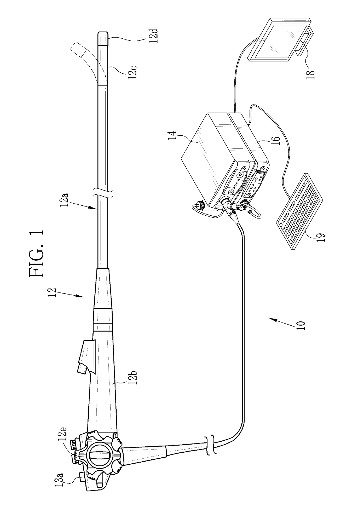
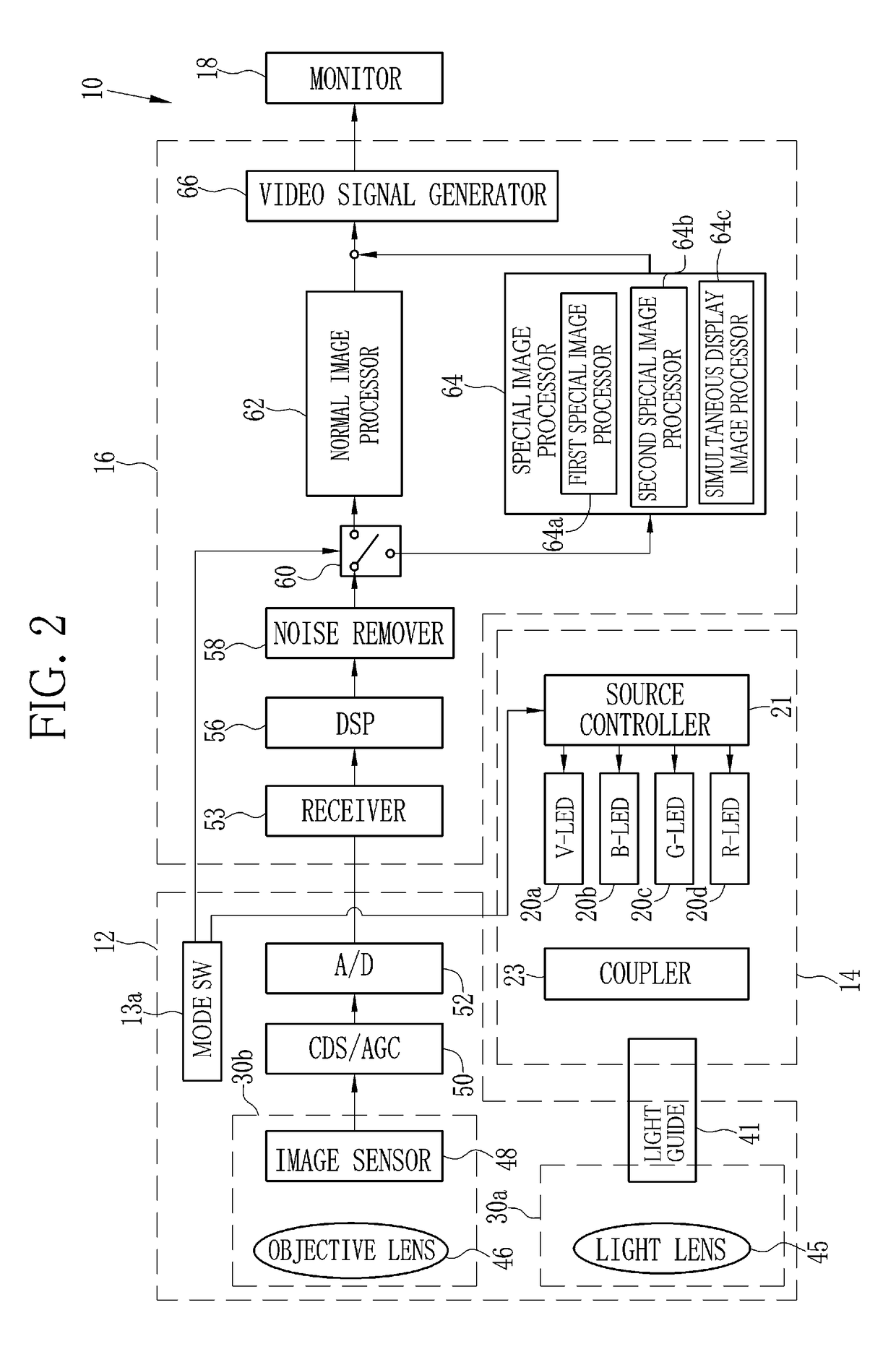
[0065]As illustrated in FIG. 1, an endoscope system 10 of a first embodiment comprises an endoscope 12, a light source device 14, a processor device 16, a monitor (display unit) 18, and a console 19. The endoscope 12 is connected optically to the light source device 14, and electrically to the processor device 16. The endoscope 12 comprises an insertion section 12a to be inserted into a body cavity, a control handle unit 12b provided at the proximal end of the insertion section 12a, a flexible portion 12c, and a distal portion 12d. The distal portion 12d is coupled to the flexible portion 12c, which is provided on the distal side of the insertion section 12a. The flexible portion 12c is bent by operating an angle knob 12e of the control handle unit 12b. The distal portion 12d is directed to a desired direction by bending the flexible portion 12c.

[0066]The control handle unit 12b is provided with the angle knob 12e and a mode switch (SW) 13a. The mode SW 13a is operated to switch am...

second embodiment

[0136]In the second embodiment, a laser and a phosphor are used, instead of the LEDs 20a to 20d of the four colors described in the first embodiment, to illuminate the object. Other than that, the configuration is the same as or similar to that in the first embodiment.

[0137]As illustrated in FIG. 32, in the light source device 14 of an endoscope system 100 according to the second embodiment, a blue laser (denoted as 445LD in FIG. 32) 104 and a blue-violet laser (denoted as 405LD in FIG. 32) 106 are provided in place of the LEDs 20a to 20d of the four colors. The blue laser 104 emits blue laser beams with the center wavelength 445±10 nm. The blue-violet laser 106 emits blue-violet laser beams with the center wavelength 405±10 nm. The light emissions from the semiconductor light emitting elements of the lasers 104 and 106 are controlled independently by a source controller 108. The light quantity ratio between the light (laser beams) from the blue laser 104 and the light (laser beams)...

third embodiment

[0143]In the third embodiment, instead of the LEDs 20a to 20d of the four colors described in the first embodiment, a broadband light source (e.g. a xenon lamp) and a rotary filter are used to illuminate the object. Instead of the color image sensor 48, a monochrome image sensor is used to image the object. The components other than those are the same as or similar to the components described in the first embodiment.

[0144]As illustrated in FIG. 35, in an endoscope system 200 of the third embodiment, a broadband light source 202, a rotary filter 204, and a filter switcher 205 are provided instead of the LEDs 20a to 20d in the light source device 14. The imaging optical system 30b is provided with a monochrome image sensor 206 with no color filter, in place of the color image sensor 48.

[0145]The broadband light source 202 is composed of a xenon lamp, a white LED, or the like, and emits white light having the wavelength range from blue to red. The rotary filter 204 comprises a normal f...


PUM


Abstract

First RGB image signals are inputted. Color difference signals Cr and Cb are calculated from the first RGB image signals. In a feature space formed by the color difference signals Cr and Cb, a first process is performed such that coordinates corresponding to a second observation area are moved to a reference area containing the origin point while coordinates corresponding to first and third observation areas are maintained unchanged. A second process is performed to move the coordinates corresponding to the first observation area and the coordinates corresponding to the third observation area away from each other.

Description

CROSS-REFERENCE TO RELATED APPLICATIONS[0001]The present application claims priority under 35 U.S.C. §119 to Japanese Patent Application No. 2014-133390, filed Jun. 27, 2014. Each of the above application(s) is hereby expressly incorporated by reference, in its entirety, into the present application.BACKGROUND OF THE INVENTION[0002]1. Field of the Invention[0003]The present invention relates to a medical image processing device for producing an image in which a difference in color between a normal site and a lesion site is enhanced, a method for operating a medical image processing device, and an endoscope system.[0004]2. Description Related to the Prior Art[0005]In medical fields, diagnoses utilizing endoscope systems have been widely performed. The endoscope system comprises a light source device, an endoscope, and a processor device. In the endoscope system, illumination light is applied from an endoscope to a region of interest (Object), and the object under the illumination lig...

Claims


Application Information

Patent Timeline
Patent Type & Authority Patents(United States)
IPC IPC(8): G06K9/00G06T5/00A61B1/00
CPCG06T5/009A61B1/00009G06T2207/10024G06T2207/10068G06T2207/30092H04N1/6027H04N1/62A61B1/000094
Inventor KURAMOTO, MASAYUKISUGIZAKI, MAKOTO
Owner FUJIFILM CORP
Why Eureka
Try Eureka