Ultrasonic cosmetic applicator

a cosmetic applicator and ultrasonic technology, applied in the direction of packaging foodstuffs, packaged goods, transportation and packaging, etc., can solve the problems of insufficient gravity feed regulation, device inability to maneuver, and cost a great deal of money for that time period, so as to reduce motion, reduce the motion, and direct small uniform droplets.

Inactive Publication Date: 2017-03-21
SONAER
View PDF8 Cites 3 Cited by
  • Summary
  • Abstract
  • Description
  • Claims
  • Application Information

AI Technical Summary

Benefits of technology

[0010]The object of the invention is to use the latest formulation of cosmetics or solutions to efficiently spray and direct small uniform droplets onto the skin's surface. It is also the object of the disclosed invention to complete the above-mentioned task without the use of an air hose, pressurized cylinder, pump, or compressor as is commonly used with airbrushing or atomization. Airbrushing is considered to be state-of-the-art in applying today's cosmetics. Normally, with an airbrush, paint or cosmetic is held in a glass container attached to the handpiece that is shaped like a pen and is easy to hold, just like Federov's invention. A compressor located in an area away from the user supplies pressurized air to the airbrush through a tube attached to the airbrush handpiece. A button is pressed activating a valve to direct air to the tip of the handpiece. This is used to pick up the solution or cosmetic to be sprayed. The liquid air mixture leaves the airbrush with a velocity and angle based on the pressure and tip configuration. The user has to constantly maneuver the airbrush to keep the tube from getting in the way of the subject being covered.
[0011]Atomizer nozzles that Sonaer makes have piezoceramics sandwiched between two end masses. The ceramics convert an alternating voltage applied to the ceramics to mechanical motion. This motion is amplified by the shape of the end mass or tip. Usually, a smaller diameter end mass amplifies the motion of the ceramics and a larger diameter end mass reduces the motion. Through the center of the atomizer nozzle is an orifice with a means of connecting a liquid line at the back of the nozzle. As liquid is pumped through the center of the probe, mechanical vibrations like that of a piston, pulverize the liquid into a fine droplets. Many droplets that reach the tip are formed into a spray. The sprays for this type of atomization are known to be finer and more uniform than air pressurized, water pressurized, and all other methods of mechanical spray. The fine spray is derived from the frequency of the nozzle. Typically, a nozzle with a higher frequency makes a smaller droplet size than one of a lower frequency. Any atomizer nozzle in the frequency range of 20,000 Hz and higher will make smaller droplets than a mechanical device that spins or vibrates at a frequency lower than 20,000 Hz, including air and liquid assisted atomization.

Problems solved by technology

This not only cost a great deal of money for that time period, but took up to a month or longer to make.
Although this device can spray liquids, we have found that a gravity feed is insufficient in regulating the flow of solution to the tip of the atomizer nozzle.
As with all devices with cords and tubing, these devices are fairly limited in their ability to maneuver without it getting in the way of the task at hand.
It would prove to be quite cumbersome to use this equipment in an environment with irregular terrain such as a battlefield or outside where there is no electricity to plug into.
In addition, Federov's invention requires a hose making it cumbersome to use, and relies on electricity, therefore making it difficult to operate in remote areas.
This configuration with the wick (7) is made like a loop and allows only a thin film of solution to be atomized, it is, therefore, not useful for large areas to be covered, as the body.
In addition, fluids are not interchangeable since the wick (7) is fixed and is not designed to be rugged for rough environments.

Method used


Image

  • Ultrasonic cosmetic applicator
  • Ultrasonic cosmetic applicator
  • Ultrasonic cosmetic applicator

Examples


Embodiment Construction

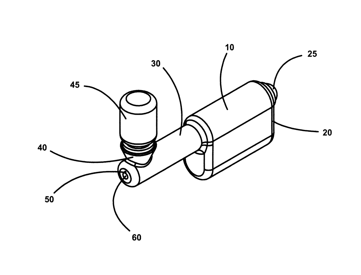
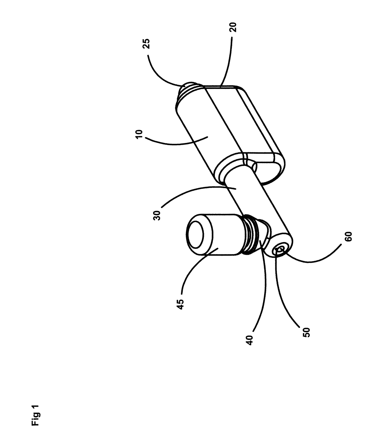
[0020]Referring now to the drawings wherein like reference characters designate like or corresponding parts throughout, there is illustrated in FIG. 1, an ultrasonic cosmetic applicator 10 for spraying atomized droplets made from cosmetic materials and solutions, onto the body or face. The cosmetic applicator 10 has a back cover 20 which covers the internal components and helps with assembly. It has attached an elastic bulb 25. The elastic bulb 25 is pressed by the users finger to apply a small pressure into the bottle 45. This pressure aids in spraying the material emitted from the distal end 60. Internal components within the cosmetic applicator 10 are loaded from the back cover 20 of the cosmetic applicator 10 up to the distal end 60 where they are secured inside the unit. Along the length of the cosmetic applicator 10 is the frontal control mechanism 30. The frontal control mechanism 30 contains many features that make the cosmetic applicator 10 function as will be further discu...


PUM


Abstract

A portable ultrasonic cosmetic applicator for spraying lip gloss, eye shadow, blush, tanning solutions, moisturizing agents, and sterilants onto the body or face. Useful for wound healing, makeup artists in the movie industry, beauty salons, and for personal use. The applicator is small and lightweight thus making it easy to use without the use of external air pressure more commonly used with airbrush spraying equipment of this type. Noisy compressors, pressurized cylinders and air lines are all eliminated. The amount of unused solutions are reduced due to its ability to produce a smaller and more uniform droplet size which, in turn, produces a fine misty spray unlike some of the more traditional applicators. Due to its lack of complexity and awkwardness, the user is able to apply liquid in a simple and graceful manner.

Description

BACKGROUND OF THE INVENTION[0001]Cosmetics have been around for over 3000 years. The Egyptians were the first to use pigments, crushed berries and leaves, and the upper class would purchase makeup from incoming travelers. This not only cost a great deal of money for that time period, but took up to a month or longer to make. At first, men would use makeup by applying galena or kohl (black eye-liner) to create an “almond shaped eye” which resembles the Falcon Eye of the God Horus. Women then began to experiment with the use of cosmetics. These substances were applied with a small stick or wooden needle having an enlarged end, creating a cotton bud shape. Along with black eye-liner, the men of ancient Egypt applied green eye shadow / paints, and a lip balm or salve colored with natural earth pigments, such as red ochre.[0002]It was said that the natives believed makeup would ward off evil spirits and protect against eye diseases and ocular infections caused by the Nile River. Kohl promo...

Claims


Application Information

Patent Timeline
Patent Type & Authority Patents(United States)
IPC IPC(8): B05B17/06A45D34/04B05B7/24B05B1/32
CPCB05B17/0676A45D34/04B05B7/244B05B1/32B05B7/2478B05B17/0607A45D2200/057A45D2200/207
Inventor CIERVO, DONALD JOHN
Owner SONAER
Why Eureka
Try Eureka