Apparatus and method to feed and preheat a metal charge to a melting furnace

a technology of metal charge and apparatus, which is applied in the direction of preheating charges, waste heat treatment, lighting and heating apparatus, etc., can solve the problems of metal charge explosion risk, compromising process functionality, and compromising the integrity of the plant, so as to improve the heat yield, prevent the risk of explosion, and increase the safety of the process

Inactive Publication Date: 2017-03-21
DANIELI & C OFF MEC SPA
View PDF7 Cites 0 Cited by
  • Summary
  • Abstract
  • Description
  • Claims
  • Application Information

AI Technical Summary

Benefits of technology

[0019]According to one form of embodiment of the present invention, the residence time is comprised between about 1 and 2 seconds, and in any case suitable to complete the combustion of the carbon monoxide, CO, into carbon dioxide CO2. The post-combustion prevents the risk of explosions inside the metal charge, increasing the safety of the process, and eliminates the need to provide downstream complex and costly apparatuses to remove the carbon monoxide before the fumes are introduced into the atmosphere. According to one solution of the invention, the post-combustion chamber is configured to also determine the sedimentation of the particulate and powders contained in the fumes.
[0020]In this way, the particulate is prevented from entering into the metal charge and blocking part of the passage of the fumes through the charge, thus obtaining a better heat yield. Moreover, the temperature of the fumes inside the post-combustion chamber is reduced from about 1,200° C.-1,350° C. to about 800-900° C., with the advantage of greatly limiting the oxidation of the metal charge and therefore less energy is expended for melting the charge in the melting furnace.
[0021]In one form of embodiment, the post-combustion chamber is disposed adjacent to, that is, at the side of and not directly below, the compartment of the tower containing the metal charge to be loaded into the furnace. This solution allows to obtain a longer residence time of the fumes compared with a solution with a post-combustion chamber disposed directly below the compartment containing scrap, in order to obtain the advantages indicated above. This solution also allows a greater freedom in modulating the residence time, for example creating obligatory paths for the fumes that can be selectively activated if particular temperature detections and / or the presence of scrap were to indicate the need for a longer or shorter residence time of the fumes before they contact the scrap.
[0025]In one variant, at least the shutter means are configured to pass from the closed condition to the open condition so as to allow a gradual and progressive discharge of the metal charge from the compartment to the transfer means.

Problems solved by technology

Some known apparatuses provide a feeding and pre-heating tower for the scrap, integrated with the furnace and disposed directly above it, such as for example in the solution shown in JP 61 015908 A, so that the scrap is discharged from above directly into the liquid bath, with obvious problems, given the quantities of metal charge fed on each occasion, even 40 tonnes, of splashing of the liquid bath and slag, given the height, even 4-5 meters, from which the metal charge is discharged, and also problems of transmission of knocks and vibrations from the tower to the furnace during these steps.
These known apparatuses have the main disadvantage, however, that the early contact of the fumes with the scrap, given their short journey, does not give the necessary time for completing the combustion of the fumes, which therefore, when they come into contact with the metal charge, are still rich in carbon monoxide because it has not been completely combusted into carbon dioxide.
This causes, first of all, the risk of explosions in the metal charge with the danger of compromising the functionality of the process, the integrity of the plant and the safety of the workers.
Furthermore, after the pre-heating step there is a presence of carbon monoxide in the fumes directed to the flue, which entails more risks of explosions along the pipes and also the need to provide appropriate and costly systems to remove the carbon monoxide before the fumes are introduced into the atmosphere, since carbon monoxide is notoriously a dangerous and toxic pollutant.
Another disadvantage of known devices is that the metal charge is put in contact with the fumes when they are still very hot, and this risks causing the small-size components of the metal charge and the components that melt at low temperatures to melt already in the first part of the feed tower.
If this melting occurs in the zone where the metal charge is introduced inside the electric furnace, compact blocks are formed that cause blockages in the conveyor pipe, with consequent long and complex interventions to reactivate the plant.
Another disadvantage of known apparatuses is that the fumes which hit the metal charge directly at high temperature, comprised between about 1,200° C. and about 1,350° C., cause high levels of oxidation of the metal charge.
The oxidation reduces the yield of the metal charge and frustrates the beneficial effect of recovering the energy of the fumes, since a greater electric energy is required in order to melt the oxidized metal charge in the furnace.
Moreover, the high losses of load that affect the fumes along their path inside the pre-heating chamber have the disadvantage of requiring apparatuses to be installed that have greater power, so as to induce the motion of the fumes from the chamber to the exit flue.

Method used


Image

  • Apparatus and method to feed and preheat a metal charge to a melting furnace
  • Apparatus and method to feed and preheat a metal charge to a melting furnace
  • Apparatus and method to feed and preheat a metal charge to a melting furnace

Examples


Embodiment Construction

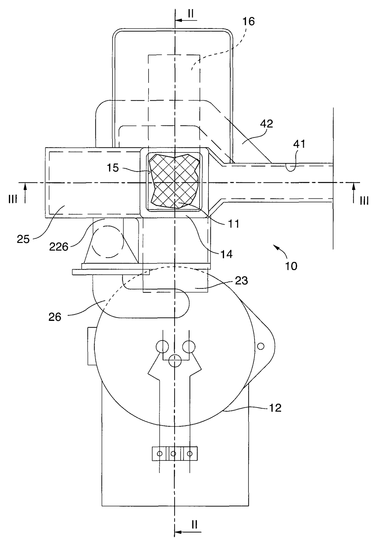
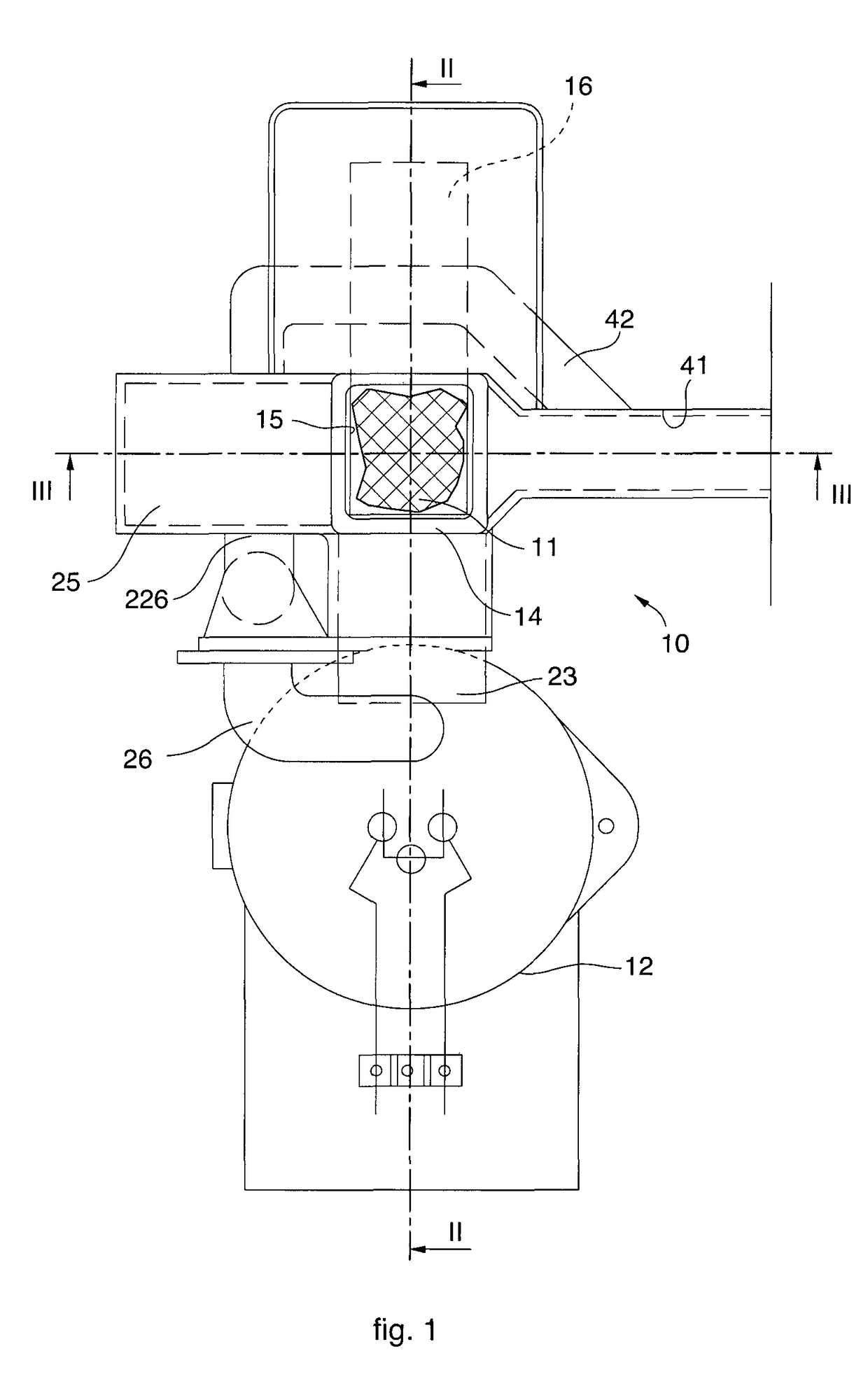
[0044]With reference to FIGS. 1, 2 and 3, an apparatus 10 according to the present invention is used to feed and pre-heat a metal charge 11, or scrap, to a melting furnace 12 of a steelworks, for example having a capacity of 100-120 t / hr.

[0045]The apparatus 10 comprises a tower 14 to feed and pre-heat the metal charge 11, with a vertical development, which is disposed at the side of and separate and autonomous from the melting furnace 12. In this way the vibrations and / or knocks originating from the tower 14 are discharged onto its own support plane 30 and onto the foundations, and not onto the melting furnace 12.

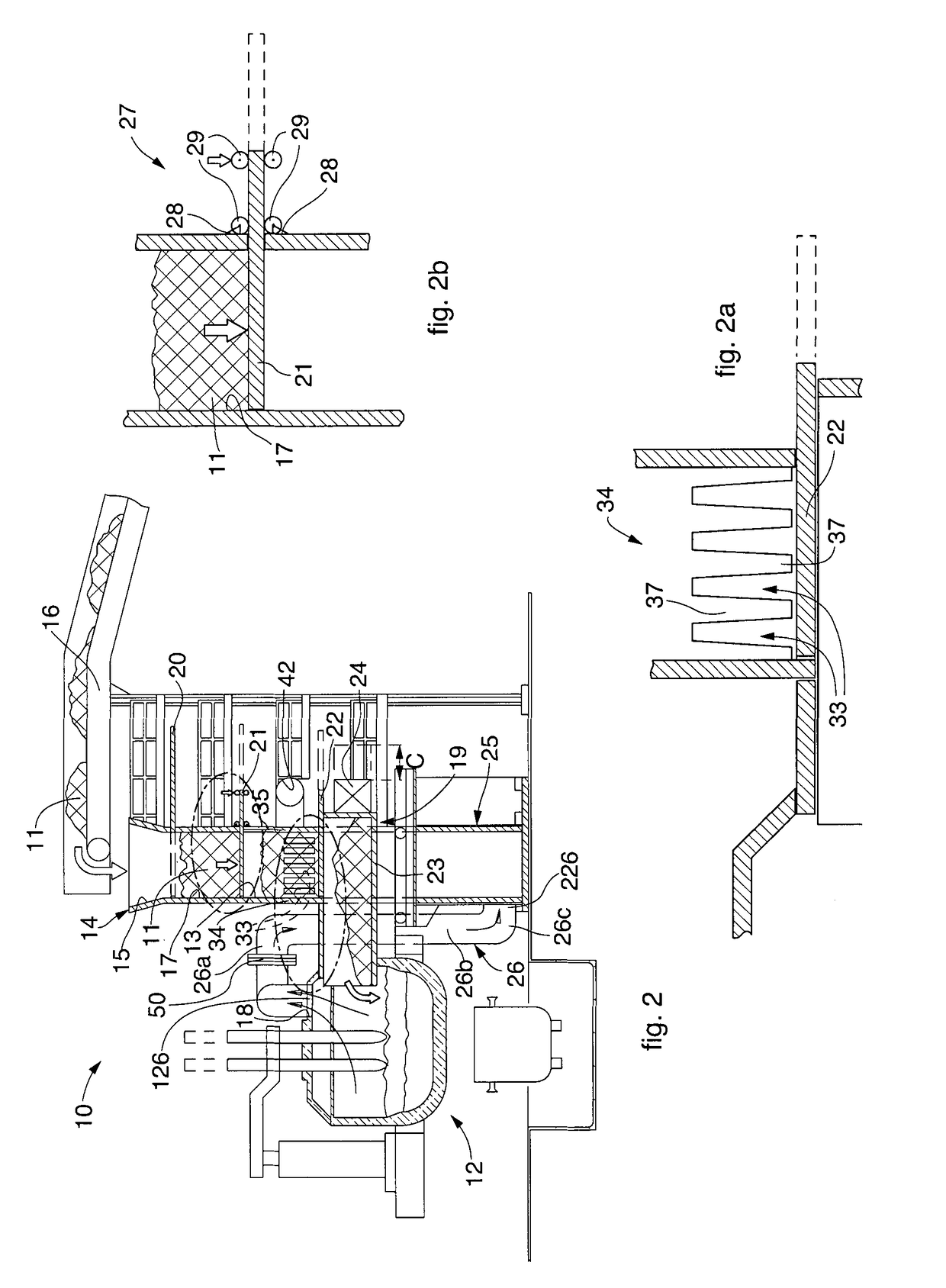
[0046]Furthermore, the apparatus 10 comprises fume conveying means to convey the fumes exiting from the melting furnace 12 to direct them toward a compartment 13 in order to pre-heat the metal charge 11.

[0047]In this case, the conveying means comprise a first pipe 26 to transport the fumes, which comprises a first end 126 connected to an exit hole 18 of the melting furnace ...


PUM


Abstract

An apparatus to feed and pre-heat a metal charge to a melting furnace of a steelworks comprises a feeding and pre-heating tower separate from the melting furnace provided with at least one compartment to temporarily contain said metal charge, transfer means to transfer said metal charge to said melting furnace and conveying means to convey the fumes exiting from the melting furnace to said compartment. The apparatus also comprises a post-combustion chamber, disposed adjacent to and below said compartment, and connected on one side to said compartment and on another side to said conveying means, the post-combustion chamber being configured to determine the expansion of the fumes introduced by the conveying means and to direct said expanded fumes toward said compartment along a path such as to determine a desired residence time of said fumes suitable to obtain at least the substantial complete combustion of the unburned gases present in said fumes.

Description

FIELD OF THE INVENTION[0001]The present invention concerns an apparatus and the corresponding method to feed and pre-heat a metal charge to the melting furnace of a steelworks.BACKGROUND OF THE INVENTION[0002]Apparatuses are known, for feeding a metal charge to the melting furnace of a steelworks. Before being fed to the furnace, the metal charge or scrap is normally pre-heated by means of the fumes produced by the melting of the metal.[0003]Some known apparatuses provide a feeding and pre-heating tower for the scrap, integrated with the furnace and disposed directly above it, such as for example in the solution shown in JP 61 015908 A, so that the scrap is discharged from above directly into the liquid bath, with obvious problems, given the quantities of metal charge fed on each occasion, even 40 tonnes, of splashing of the liquid bath and slag, given the height, even 4-5 meters, from which the metal charge is discharged, and also problems of transmission of knocks and vibrations f...

Claims


Application Information

Patent Timeline
Patent Type & Authority Patents(United States)
IPC IPC(8): F27D13/00C21C5/52F27D3/00F27B3/18C21C5/00C21C5/56F27D17/00
CPCF27D13/00C21C5/00C21C5/527C21C5/565F27B3/186F27D3/00F27D13/002F27D17/002Y02P10/216Y02P10/20
Inventor POLONI, ALFREDO
Owner DANIELI & C OFF MEC SPA
Why Eureka
Try Eureka