Loop heat pipe evaporator including a second heat pipe
- Summary
- Abstract
- Description
- Claims
- Application Information
AI Technical Summary
Benefits of technology
Problems solved by technology
Method used
Image

Examples
Embodiment Construction
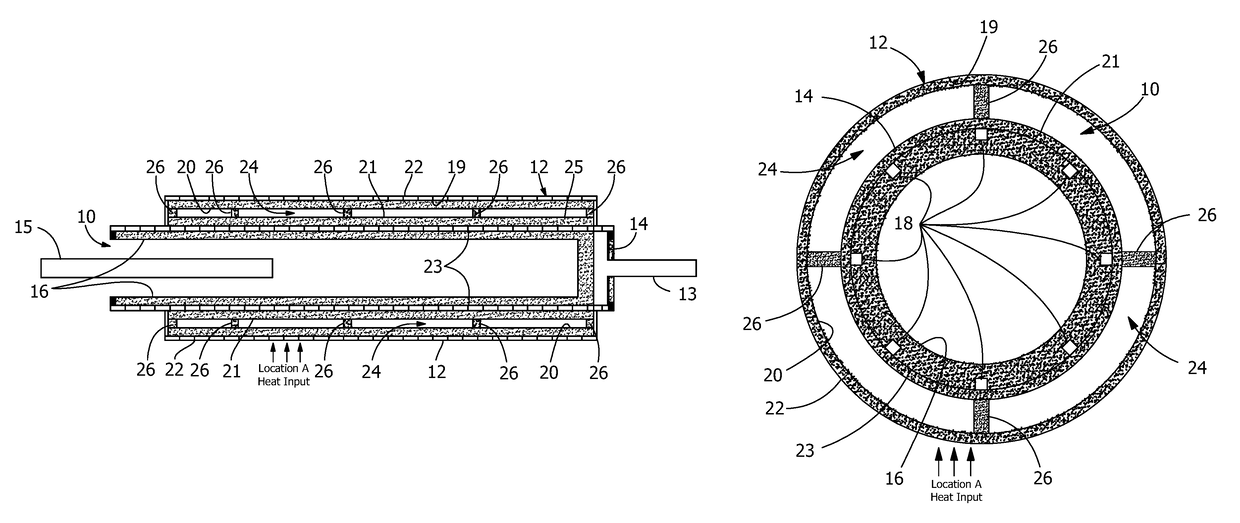
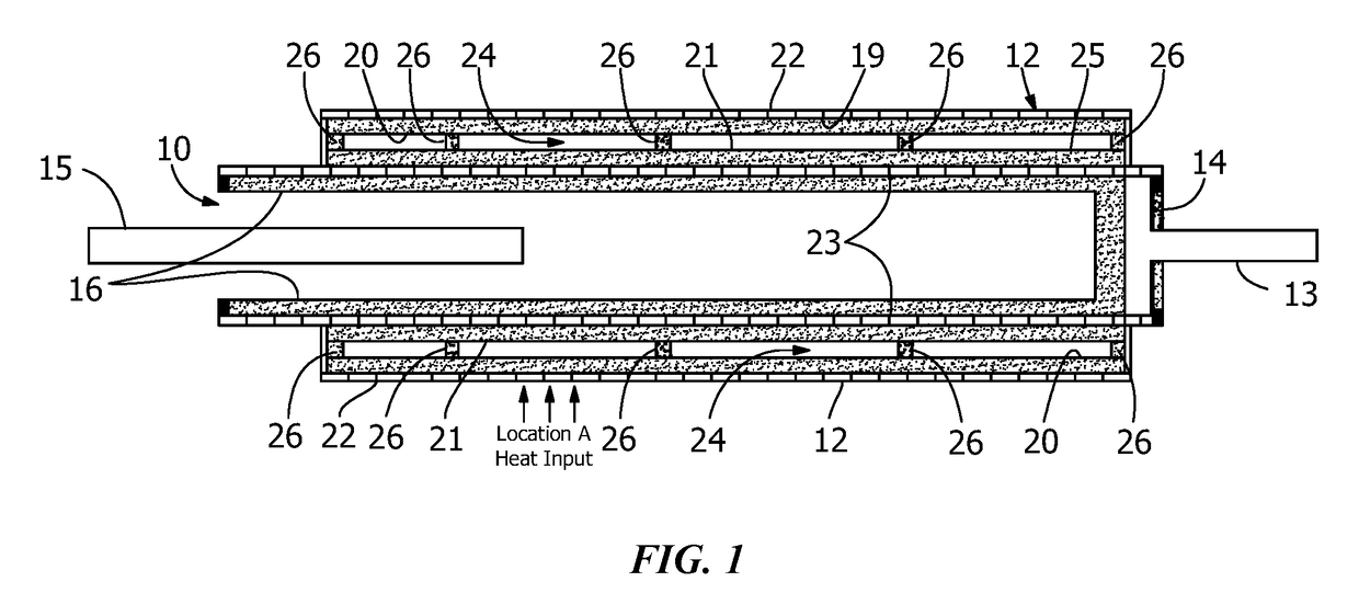
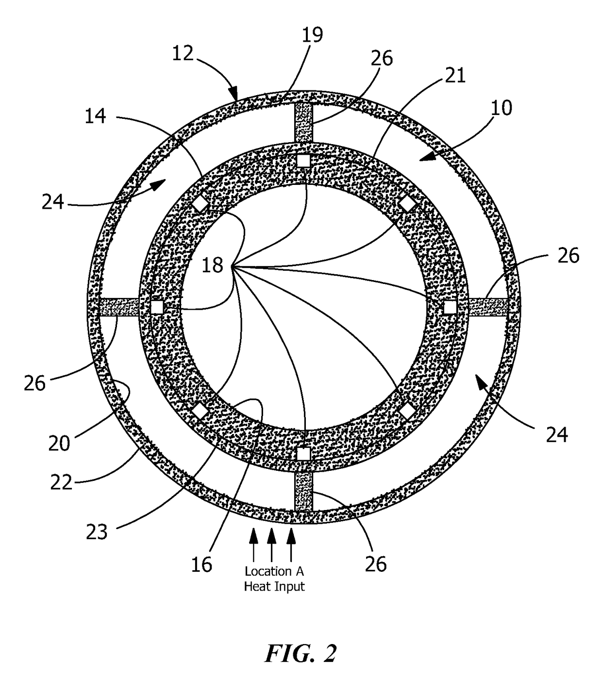
[0011]FIG. 1 is a longitudinal cross section view of the preferred embodiment of the invention along the axis of loop heat pipe evaporator 10, and FIG. 2 is a cross section view of the preferred embodiment of the invention across the axis of loop heat pipe evaporator 10.
[0012]As shown in both figures, heat pipe 12 is attached to casing wall 14 of evaporator 10, and is constructed so that it uses evaporator casing wall 14 as one wall of heat pipe 12. However, heat pipe 12 can also be constructed as a separate structure which is bonded to casing wall 14 of evaporator 10. It should also be appreciated that although in FIG. 2 evaporator 10 is shown as a cylinder and heat pipe 12 as an annular structure around cylindrical evaporator 10, both evaporator 10 and heat pipe 12 can have different shapes.
[0013]Loop heat pipe evaporator 10 is shown with the conventional structure of such an evaporator. Prior art loop heat pipe evaporators typically have cylindrical casings 14 with capillary wick...
PUM
 Abstract
Description
Claims
Application Information
 - R&D Engineer
- R&D Manager
- IP Professional
- Industry Leading Data Capabilities
- Powerful AI technology
- Patent DNA Extraction
Browse by: Latest US Patents, China's latest patents, Technical Efficacy Thesaurus, Application Domain, Technology Topic.
© 2024 PatSnap. All rights reserved.Legal|Privacy policy|Modern Slavery Act Transparency Statement|Sitemap