Multi-port pumping system for substrate processing chambers

a technology of substrate processing and pumping system, which is applied in the direction of cleaning using liquids, instruments, applications, etc., can solve the problems of limited flow capacity that cannot accommodate increased, limited rate at which the activated cleaning gas flows into the deposition chamber, and reduced cleaning efficiency of the activated cleaning gas

Inactive Publication Date: 2009-05-14
APPLIED MATERIALS INC
View PDF82 Cites 201 Cited by
  • Summary
  • Abstract
  • Description
  • Claims
  • Application Information

AI Technical Summary

Benefits of technology

[0013]In one specific embodiment, the invention utilizes three vacuum interface ports available on the throttle body of a conventional semiconductor deposition chamber. The three ports, which are upstream of a turbo molecular pump, are fluidly coupled together and to the exhaust foreline to allow increased pumping capability without the need for a major and expensive redesign of existing chambers. Embodiments of the invention also allow existing chambers to be retrofitted from a single port foreline design to a two or three port foreline design to increase the pumping capacity of the existing chamber.

Problems solved by technology

The rate at which the activated cleaning gas flows from the RPS into the deposition chamber is often limited by the construction of the RPS.
The port is of a fixed size and has a limited flow capacity that cannot accommodate increased input flows of the cleaning gas beyond a certain point without an increase in the chamber pressure.
When a higher flow RPS unit that can generate flow of activated cleaning gas in the range of 10 to 15 SLM, the single port foreline cannot remove the gas at a fast enough rate and the chamber pressure rises above an ideal range resulting in a decrease in the cleaning efficiency of the activated cleaning gas.
This limitation on the input flow rate of cleaning gas results in longer chamber cleaning times and reduces its throughput or productivity.

Method used


Image

  • Multi-port pumping system for substrate processing chambers
  • Multi-port pumping system for substrate processing chambers
  • Multi-port pumping system for substrate processing chambers

Examples


Embodiment Construction

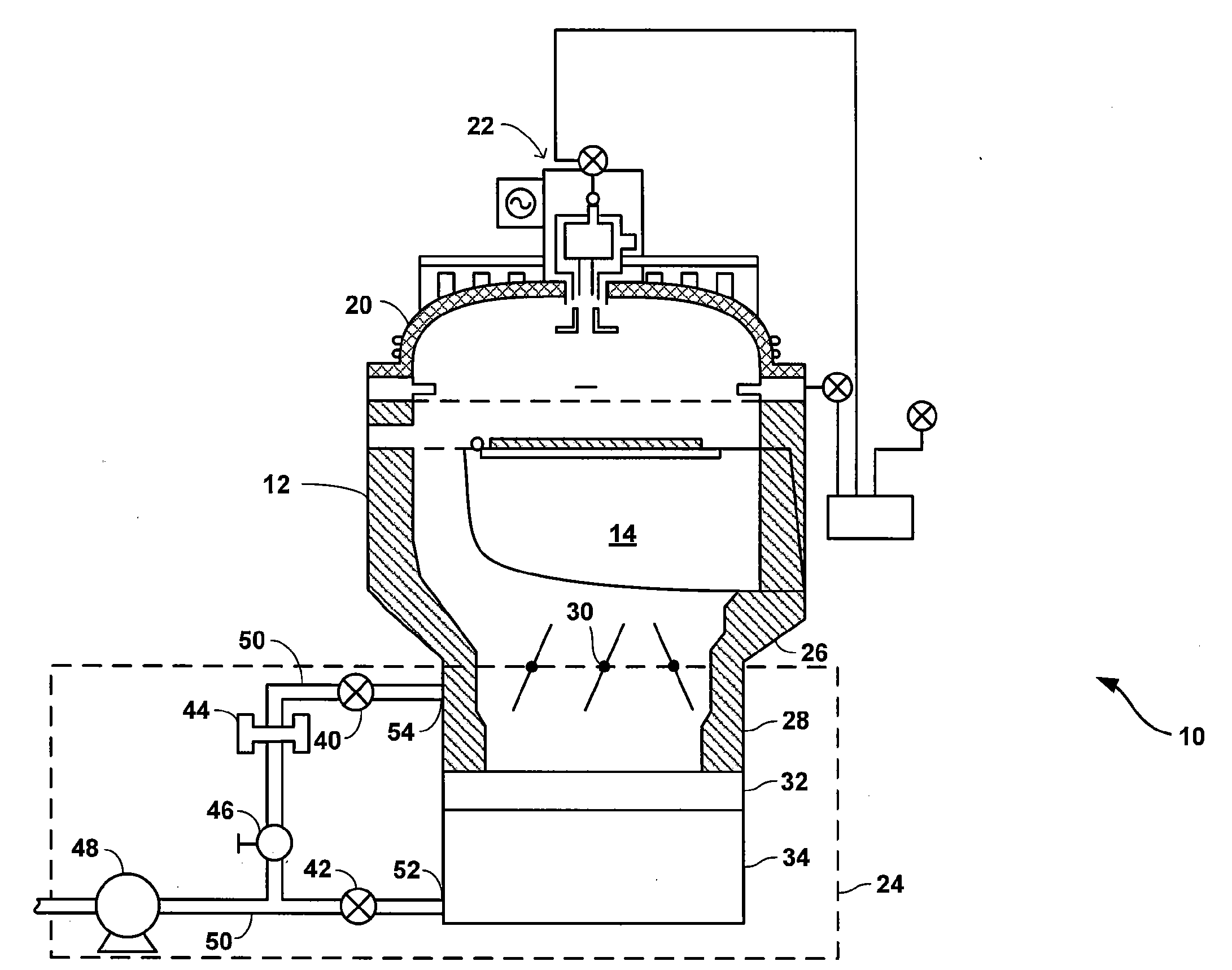
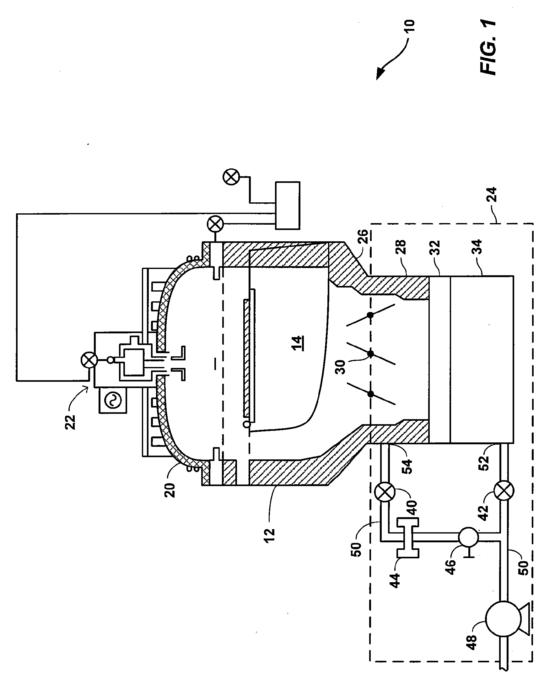
[0020]FIG. 1 is a simplified cross-sectional view of a high density plasma chemical vapor deposition (HDP-CVD) system 10 in which the techniques according to the present invention can be employed to increase the pumping capacity of system 10 during a chamber clean operation. CVD system 10 includes, among other elements, a chamber body 12, a substrate support 14 (e.g., an electrostatic chuck), gas nozzles 16, 18, a chamber dome 20, a remote plasma cleaning system 22 and a vacuum system 24. Chamber body 12, dome 20 and substrate support 14 combine to define a processing region 15 in which a substrate 2 is positioned during a substrate processing operation, such as a chemical vapor deposition operation. For convenience, numerous features of system 10 that are not directly relevant to the invention have been omitted from FIG. 1 and are not discussed herein. For example, system 10 includes a gas distribution system that delivers process gases to gas nozzles 16, 18, as well as source and ...


PUM

PropertyMeasurementUnit
pressureaaaaaaaaaa
degree angleaaaaaaaaaa
pressuresaaaaaaaaaa

Abstract

An exhaust foreline for purging fluids from a semiconductor fabrication chamber is described. The foreline may include a first, second and third ports independently coupled to the chamber. A semiconductor fabrication system is also described that includes a substrate chamber that has a first, second and third interface port. The system may also include a multi-port foreline that has a first, second and third port, where the first foreline port is coupled to the first interface port, the second foreline port is coupled to the second interface port, and the third foreline port is coupled to the third interface port. The system may further include an exhaust vacuum coupled to the multi-port foreline.

Description

CROSS-REFERENCES TO RELATED APPLICATIONS[0001]The present application claims benefit under 35 USC 119(e) of U.S. provisional Application No. 60 / 986,332, filed on Nov. 8, 2007, entitled “Multi-Port Pumping System For Reduced Cleaning Pressure In Dielectric Deposition Chambers,” the content of which is incorporated herein by reference in its entirety.BACKGROUND OF THE INVENTION[0002]One of the primary steps in the fabrication of modern semiconductor devices is the formation of a layer, such as a silicon oxide layer, on a substrate or wafer. As is well known, such a layer can be deposited by chemical vapor deposition (CVD). In a conventional thermal CVD process, reactive gases are supplied to the substrate surface where heat-induced chemical reactions take place to form the desired film. In a conventional plasma CVD process, a controlled plasma is formed using, for example, radio frequency (RF) energy or microwave energy to decompose and / or energize reactive species in reactant gases t...

Claims


Application Information

Patent Timeline
Patent Type & Authority Applications(United States)
IPC IPC(8): C23C16/00G05D7/00
CPCC23C16/4412H01J37/32834Y10S134/902H01L21/67069H01J37/32862Y10T137/85978Y10T137/87571H01L21/02H01L21/00
Inventor RASHEED, MUHAMMAD M.LUBOMIRSKY, DMITRYSANTOSA, JAMES
Owner APPLIED MATERIALS INC
Why Eureka
Try Eureka