Multi-receiver communication system with distributed aperture antenna

a communication system and antenna technology, applied in the field of antennas, can solve the problems of increasing the likelihood of interference with nearby aircraft and/or airport systems, creating an uneven field distribution, and more opportunities for field leakage outside the cabin, so as to reduce the distance between the antenna and the receiver, reduce the overall power requirements of the antenna, and reduce the propagation mode and multi-path effect.

Inactive Publication Date: 2007-08-02
HAMILTON SUNDSTRAND CORP
View PDF67 Cites 198 Cited by
  • Summary
  • Abstract
  • Description
  • Claims
  • Application Information

AI Technical Summary

Benefits of technology

[0007] The invention is directed to an inventive antenna structure having distributed apertures and a communication system incorporating the inventive distributed aperture antenna. In one embodiment, the distributed aperture antenna is a coaxial cable having apertures distributed along an outer shield of the cable. In another embodiment, the distributed aperture antenna is in the form of a parallel plate waveguide having apertures distributed along the length of the waveguide. The apertures allow radiated energy to leak from the cable or waveguide antenna and form low-power, localized electric fields that can couple receivers to the antenna. Generating multiple localized electric fields rather than a single, high-power electric field reduces the distance between the antenna and the receiver, thereby reducing propagation modes and multi-path effects that normally occur over longer distances. The multiple electric fields also ensure that field strength is distributed evenly throughout the communication system.
[0008] Further, because the inventive distributed aperture antenna generates a plurality of low-power electric fields rather than a single, high-power electric field, the overall power requirements for the antenna are lowered, reducing the likelihood that the electric field will leak beyond the desired boundaries of the electric fields and interfere with other communication systems.
[0009] As a result, the inventive distributed aperture antenna enhances wireless data transmission capability within an aircraft cabin, room, vehicle, or any other space where multiple users may be accessing the communication system in an enclosed space.

Problems solved by technology

However, using a single source antenna creates an uneven field distribution, such as a concentrated field close to the source antenna and a weakened field farther away from the source antenna.
Increasing the field strength at the edges of the source antenna's field may improve receiver coupling throughout the cabin, but this creates more opportunities for field leakage outside of the cabin and increases the likelihood of interference with nearby aircraft and / or airport systems.
Further, receivers operating in areas far from the source antenna may experience reductions in the effective bandwidth of the communication system due to multi-path effects at the receivers caused by uneven propagation mode generation.
Additionally, longer signal paths, particularly in an enclosed space housing multiple users, increases the likelihood that signals will bounce off the walls of the enclosed space and repeatedly reflect inside the space, creating further interference.
Although it may be possible to incorporate additional antennas in the aircraft to reduce the effects of uneven field distribution and mode generation, the fields created by multiple antennas still are not evenly distributed and still create undesirable concentrations of the electric field close to the antenna.
Multiple antennas also be costly and complex to install, making them too impractical for widespread use.

Method used


Image

  • Multi-receiver communication system with distributed aperture antenna
  • Multi-receiver communication system with distributed aperture antenna
  • Multi-receiver communication system with distributed aperture antenna

Examples


Embodiment Construction

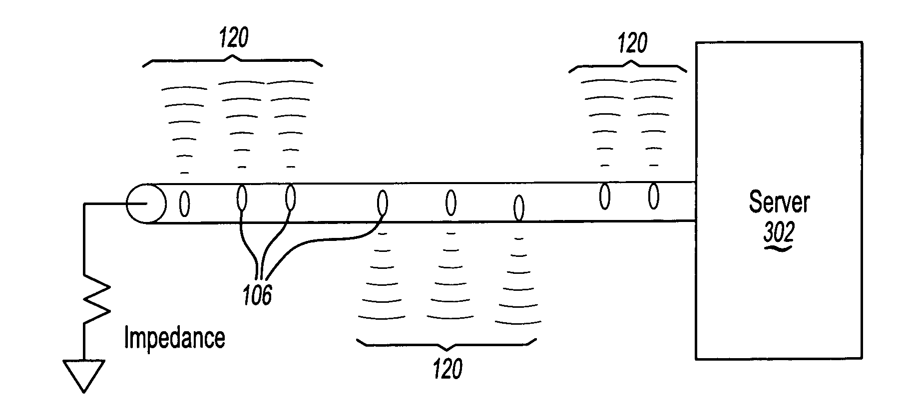
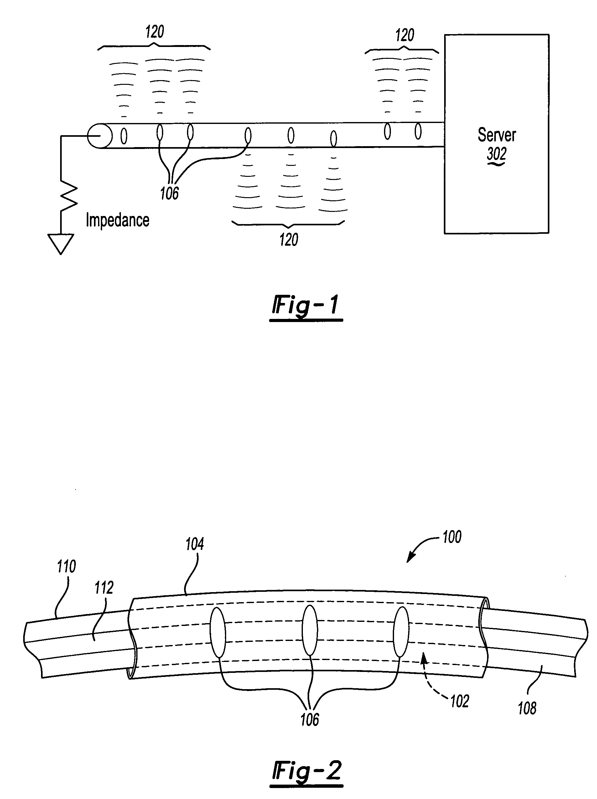
[0016]FIGS. 1 through 3 illustrate a distributed aperture antenna 100 structure according to two possible embodiments of the invention. In the embodiment shown in FIG. 2, the antenna 100 is a coaxial cable that includes a conductive core 102 and an insulating shield 104. The shield has a plurality of apertures 106, which serve as an energy leakage path for the conductor 104. The conductive core 102 in this embodiment includes an inner conductor 108 and an outer conductor 110 separated by a dielectric 112. In one embodiment, the antenna 100 is an air-type coaxial cable supported by a helical dielectric band. This type of antenna structure minimizes the overall weight of the antenna 100 as well as reduces insertion losses at the frequencies in which the antenna 100 may be used.

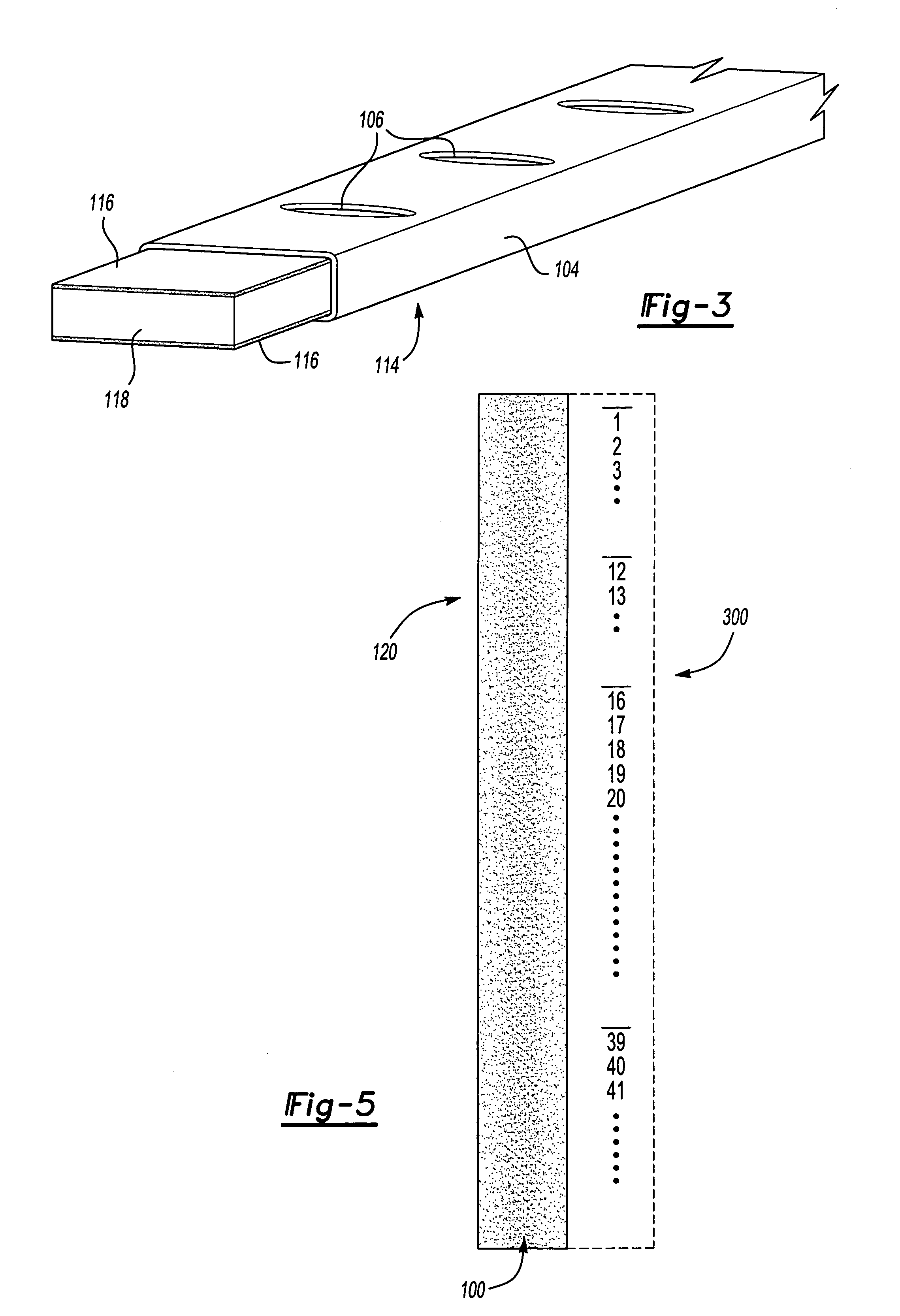
[0017]FIG. 3 illustrates another possible embodiment for the inventive antenna 100. In this embodiment, the antenna 100 is in the form of a parallel plate waveguide 114 having two strips of conducting material ...


PUM


Abstract

A multi-user wireless communication system for use in an enclosed space includes a distributed aperture antenna having multiple apertures distributed along an outer shield of the antenna. The apertures allow radiated energy to leak from the antenna and form low-power, localized electric fields that can couple receivers to the antenna. The multiple electric fields ensure that the electric field strength is distributed evenly throughout the communication system. The low-power electric fields also reduce the likelihood of electric field leakage that may cause interference with other communication systems outside the enclosed space.

Description

TECHNICAL FIELD [0001] The invention relates to antennas, and more particularly to an antenna for use in a wireless network installed in a multi-passenger conveyance or other enclosed space. BACKGROUND OF THE INVENTION [0002] With the increase in wireless communication methods as well as business travel, there has been a growing demand for systems and services that can connect travelers to their desired data, such as e-mail and Internet web sites, while they are aboard an aircraft, train, or other multi-passenger conveyance. For simplicity, the description below will focus on wireless networks in an aircraft cabin environment, but the invention can apply to any environment where multiple users may access the network at the same time in an enclosed environment, including buildings, vans, buses, and other similar locations. Further, although the description below focuses on providing wireless links to carry data for aircraft functions, such as health and prognostics, security, in-flig...

Claims


Application Information

Patent Timeline
Patent Type & Authority Applications(United States)
IPC IPC(8): H01Q1/52B64D11/00H01Q1/00H01Q13/20H04B5/00H04B17/00
CPCB64D11/0015H01Q1/007H04B17/354H01Q13/203H01Q13/20Y02T50/40
Inventor PRISTAS, JAMESHUGHES, DAN
Owner HAMILTON SUNDSTRAND CORP
Why Eureka
Try Eureka