Method for determining a magnetic resonance control sequence, and magnetic resonance system operable according to the control sequence

a magnetic resonance and control sequence technology, applied in the direction of reradiation, measurement using nmr, instruments, etc., can solve the problem that valueable image information located (for example) under a stripe may not be detected

Active Publication Date: 2017-03-21
SIEMENS HEALTHCARE GMBH
View PDF10 Cites 2 Cited by
  • Summary
  • Abstract
  • Description
  • Claims
  • Application Information

AI Technical Summary

Benefits of technology

[0013]Through the targeted marking of the image data by saturation in well-defined, precisely predetermined marking regions depending on the subject structure, and no longer globally by a stripe pattern over the entire image as before, it is possible to make defined, important structures and their variation over the image series (for example the wall of a heart, etc.) better visible, and to simultaneously ensure that other structures are not unnecessarily occluded by a pattern, whereby image information is lost. The evaluation of the data in automatic or semi-automatic form is also significantly simpler.
[0018]The invention thus also encompasses a non-transitory, computer-readable data storage medium encoded with programming instructions that can be loaded directly into a memory of a control sequence determination device and / or a structural data determination device, with program code segments in order to execute all steps of the method according to the invention in the control sequence determination device and / or structural data determination device. Such a realization in software has the advantage that existing devices that are used to determine control sequences and / or to determine structural data by a suitable evaluation of the acquired image series can also be suitably modified by implementation of the programming instructions in order to determine control sequences or, respectively, structural data in the manner according to the invention.

Problems solved by technology

These global stripes or grids overlaying the entire individual MR images have an extraordinarily interfering effect on a normal viewing of the images, and in addition valuable image information that (for example) is located under a stripe may possibly not be detected.

Method used


Image

  • Method for determining a magnetic resonance control sequence, and magnetic resonance system operable according to the control sequence
  • Method for determining a magnetic resonance control sequence, and magnetic resonance system operable according to the control sequence
  • Method for determining a magnetic resonance control sequence, and magnetic resonance system operable according to the control sequence

Examples


Embodiment Construction

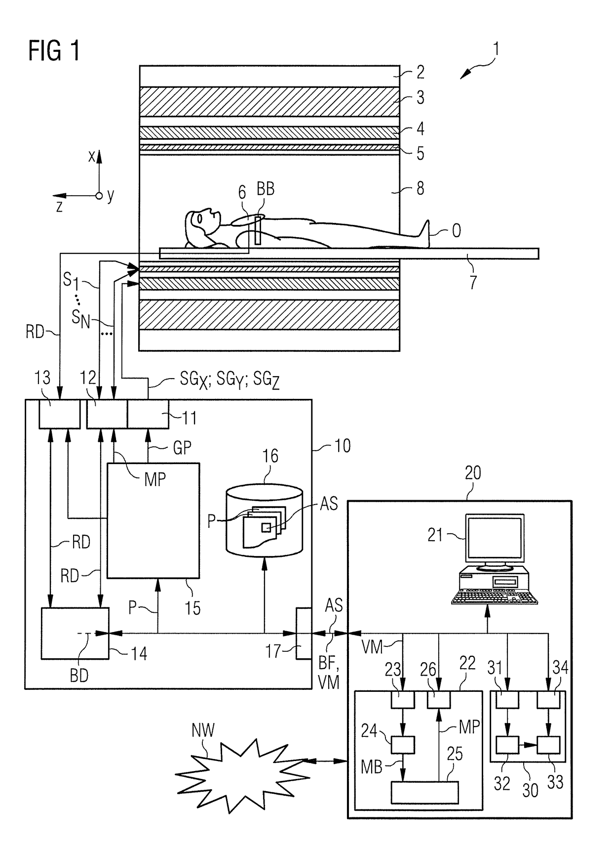
[0032]A magnetic resonance system 1 is schematically depicted in FIG. 1. The system 1 includes the actual magnetic resonance scanner 2 with an examination space 8 or patient tunnel located therein. A bed 7 can be moved into this patient tunnel 8, such that during an examination an examination subject O (for example a patient lying atop the bed 7) can be supported at a defined position within the magnetic resonance scanner 2 relative to the magnet system and radio-frequency system arranged therein and / or is movable between different positions during a measurement.

[0033]Basic components of the magnetic resonance scanner 2 are a basic field magnet 3, a gradient system 4 with magnetic field gradient coils in order to apply arbitrary magnetic field gradients in the x-, y- and z-directions, as well as a whole-body radio-frequency coil 5 (or, respectively, body coil). The reception of magnetic resonance signals produced in the examination subject O can take place via the whole-body coil 5 ...


PUM


Abstract

In a method and control sequence determination device for determination of a magnetic resonance system control sequence to generate an image series of a defined image region of an examination subject, the control sequence includes a multichannel pulse train with multiple individual RF pulse trains to be emitted in parallel by the magnetic resonance system via different independent radio-frequency transmission channels. The multichannel pulse train includes an excitation pulse to excite the image region and a subsequent number of refocusing pulses in order to respectively excite an echo signal to acquire raw data for an image of the image series. At least one defined marking region in the image region is determined depending on a subject structure to be depicted in the image region, and the multichannel pulse train is determined such that a saturation is achieved at or in the marking regions before the excitation pulse.

Description

BACKGROUND OF THE INVENTION[0001]Field of the Invention[0002]The invention concerns a method to determine a magnetic resonance system control sequence to generate an image series of a defined image region of an examination subject. The magnetic resonance system control sequence includes a multichannel pulse train with multiple individual RF pulse trains to be emitted in parallel by the magnetic resonance system via different independent radio-frequency transmission channels of a transmission device. The multichannel pulse train includes an excitation pulse to excite the image region, as well as a subsequent number of refocusing pulses in order to respectively excite an echo signal to acquire raw data for an image of the image series. Furthermore, the invention concerns a method to generate an image series of a defined image region using such a magnetic resonance system control sequence, and a method to determine structural data of an examination subject based on such an image series...

Claims


Application Information

Patent Timeline
Patent Type & Authority Patents(United States)
IPC IPC(8): G01V3/00G01R33/563G01R33/483G01R33/561
CPCG01R33/56333G01R33/4838G01R33/5612
Inventor RITTER, DIETER
Owner SIEMENS HEALTHCARE GMBH
Why Eureka
Try Eureka