
Dynamic enhanced and diffuse broad spectrum UVC or alternative controlled ionizing radiation source emitters for mobile and fixed placement disinfection of clinical surfaces

a broad spectrum, ionizing radiation source technology, applied in diffusing elements, lighting and heating apparatuses, instruments, etc., can solve the problems of compromising effective disinfection, compromising effective disinfection, repositioning during use is costly and/or disruptive, etc., and achieves enhanced energy diffusion

Inactive Publication Date: 2017-03-28
NEWHAM PAUL
View PDF32 Cites 56 Cited by
  • Summary
  • Abstract
  • Description
  • Claims
  • Application Information

AI Technical Summary

Benefits of technology

The present invention is a device that uses UV-C light emitting diodes (LEDs) or alternative UV-C emission components of incrementally differing wavelengths embedded in a reflective nacel that forms the surface of a rotatable spherical or hemispherical structure. The device generates extreme broad spectrum UV-C energy that is evenly diffused over the treatment area through re-sequencing each UV-C LED emitter in adjacent pods while rotating and strobing the entire spherical or hemispherical support structure. White light LEDs are also incorporated within each reflective nacel to help with positioning the UV-C emitter head relative to treatment surfaces. The device control units are individually digitally encoded to prevent system cross-talk.

Problems solved by technology

While gaining awareness in the healthcare environment, present UV-C emission devices suffer the inherent problems of: (a) Fundamental design limitations resulting in difficult aiming of the device energy field with respect to critical high-touch patient surfaces which can end up being shadowed in blind spot locations, greatly compromising effective disinfection.
Attempts to rectify this problem with reflective room coatings or frequent system repositioning during use are costly and / or disruptive; (b) limited UV-C spectrum emission through the use of mercury discharge or xenon emitters thereby compromising effective disinfection of the wide assortment of prospective HAI pathogens (including MRSA, C. difficile, Acinetobacter, A. baumanni, Vancomycin resistant enterobacter VRE, etc.).
While many current UV-C systems exhibit a limited wavelength spectrum of around 253 nm, optimal UV-C disinfection effectiveness occurs through broad as possible use of a 200-280 nm emission spectrum; (c) present systems are heavy, bulky semi-transportable devices presenting significant operator problems in transportation, set-up and operation.
They may also lack on-board power and adequate, automated security of operation.
They are also relatively costly, thereby limiting their use.

Method used


Image

  • Dynamic enhanced and diffuse broad spectrum UVC or alternative controlled ionizing radiation source emitters for mobile and fixed placement disinfection of clinical surfaces
  • Dynamic enhanced and diffuse broad spectrum UVC or alternative controlled ionizing radiation source emitters for mobile and fixed placement disinfection of clinical surfaces
  • Dynamic enhanced and diffuse broad spectrum UVC or alternative controlled ionizing radiation source emitters for mobile and fixed placement disinfection of clinical surfaces

Examples


Embodiment Construction

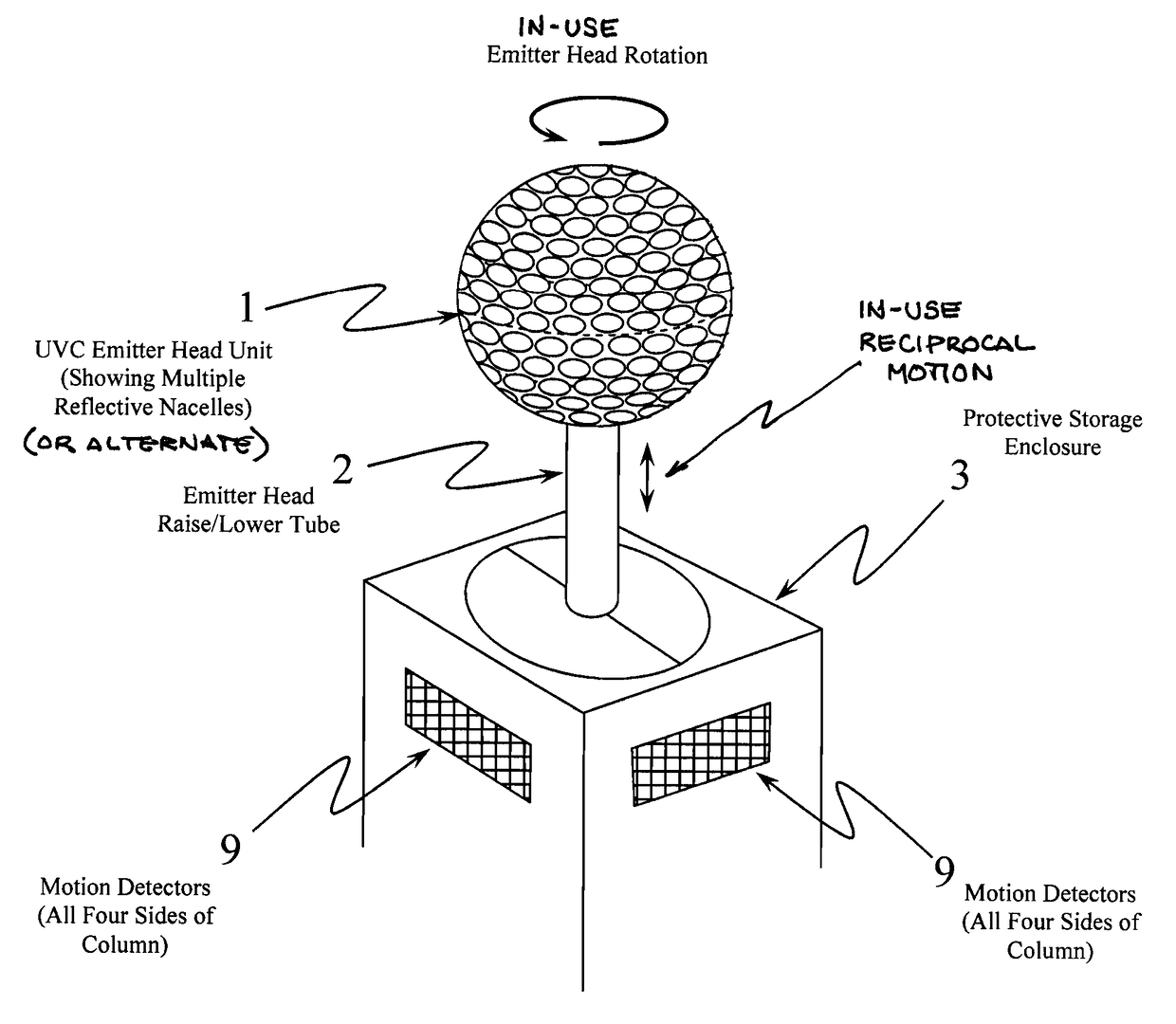
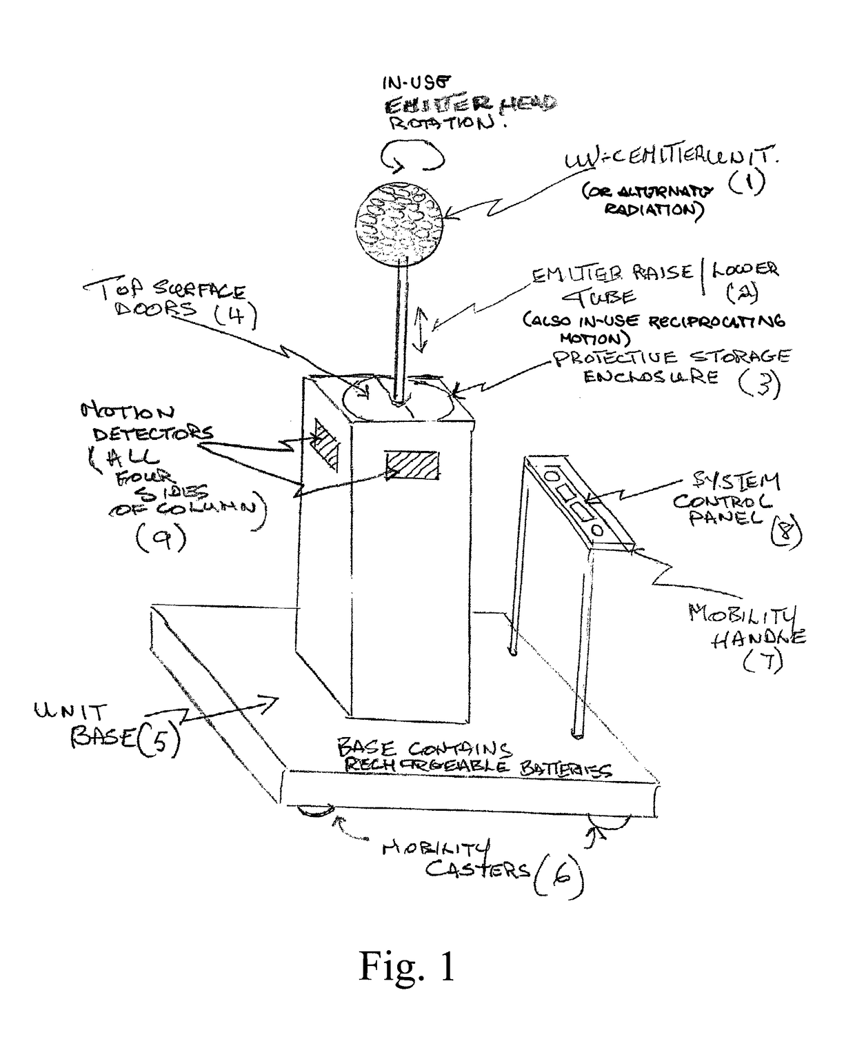
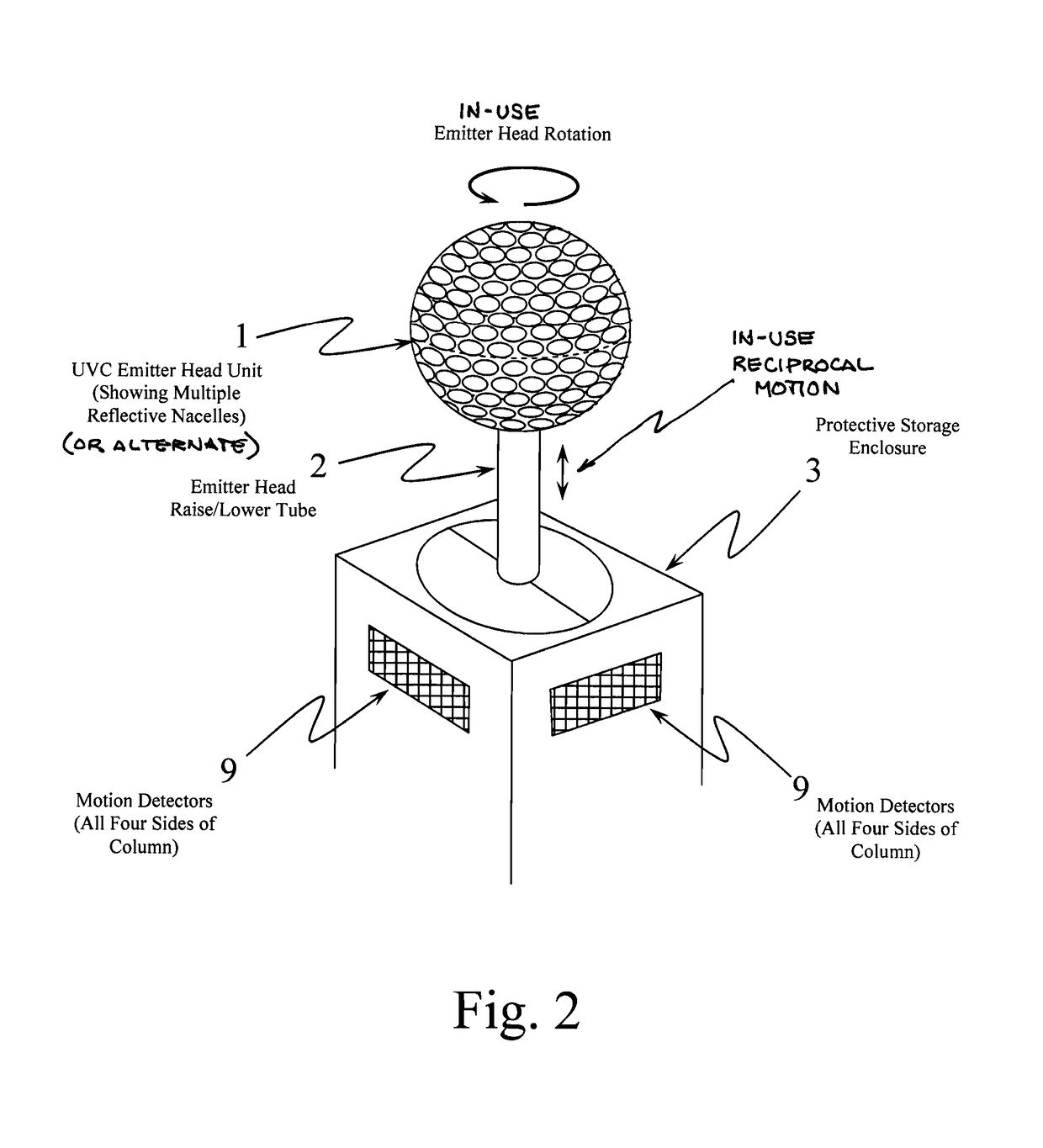
[0027]FIGS. 1 & 2 show a general, and close-up view of a free-standing, mobile embodiment of the device, where (1) is a spherical rotatable UV-C emitting structure whose surface consists of densely packed reflective nacels incorporating UV-C energy emitting LEDs or equivalent, concurrent with white light emitter components. Structure (1) is connected to, and supported by, support tube (2), the lower end of which descends into vertical enclosure tower (3), which also functions as a protective enclosure for spherical UV-C emitter (1) when not in use in conjunction with top surface retractable enclosure doors (4). Vertical enclosure tower (3) also contains embedded motion detection sensors (9) on all four sides.

[0028]Vertical enclosure tower (3) is, in turn, supported by, and attached to unit base structure (5), which permits device mobility through casters (6). Base structure (5) also contains internal rechargeable battery / AC line driven system power supplies.

[0029]Operator mobility c...


PUM

PropertyMeasurementUnit
time delayaaaaaaaaaa
wavelengthsaaaaaaaaaa
energy diffusionaaaaaaaaaa

Abstract

A system providing effective, broad spectrum UV-C or other ionizing radiation clinical surface disinfection, high intensity UV-C light emitting diodes (LEDs) of incrementally differing wavelengths are sequentially embedded in densely packed reflective nacels (cups or pockets) forming the surface of a rotating spherical or hemispherical structure. A combination of UV-C emitter component location and activation with the rotational and reciprocal elevation functions of such structures produces complete and continuous environmental overlapping UV-C energy scattering.

Description

CROSS REFERENCES TO RELATED APPLICATIONS[0001]This application claims the benefit under Title 35 United States Code §119(e) of U.S. Provisional Patent Application Ser. No. 61 / 915,450 filed Dec. 12, 2013, the full disclosure of which is incorporated herein by reference.BACKGROUND OF THE INVENTION[0002]1. Field of the Invention[0003]To provide effective, broad spectrum UV-C or alternative controlled ionizing radiation source clinical surface disinfection, high intensity light emitting diodes (LEDs) of incrementally differing wavelengths are sequentially embedded in densely packed reflective nacels (geometrically shaped cups or depressions) forming the surface of a rotating spherical or hemispherical structure. The combination of emitter component location and activation with the rotational and reciprocal elevation functions of such structures produces complete and continuous environmental overlapping energy scattering. Ultraviolet C light (UV-C or UVC) is an ISO Standard for short wav...

Claims


Application Information

Patent Timeline
Patent Type & Authority Patents(United States)
IPC IPC(8): H01J37/00G02B5/02A61L2/10F21V14/04F21V5/04F21V13/06A61L2/24
CPCA61L2/10F21V5/045F21V13/06F21V14/04G02B5/0231G02B5/0284A61L2/24
Inventor NEWHAM, PAUL
Owner NEWHAM PAUL
Learn More