Supercharge Your Innovation With Domain-Expert AI Agents!

Composite cable

a technology of composite cables and conductive wires, applied in the direction of optical elements, printed circuit non-printed electric components association, instruments, etc., can solve the problems of high flexibility, increased manufacturing cost, and reduced flexibility, so as to reduce manufacturing costs, simplify the structure, and improve reliability

Active Publication Date: 2017-03-28
MOLEX INC
View PDF9 Cites 1 Cited by
  • Summary
  • Abstract
  • Description
  • Claims
  • Application Information

AI Technical Summary

Benefits of technology

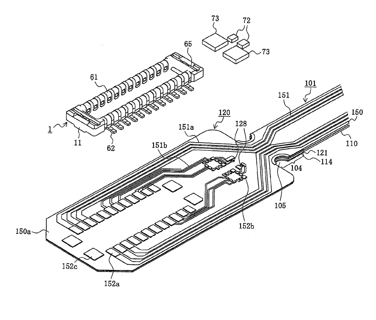
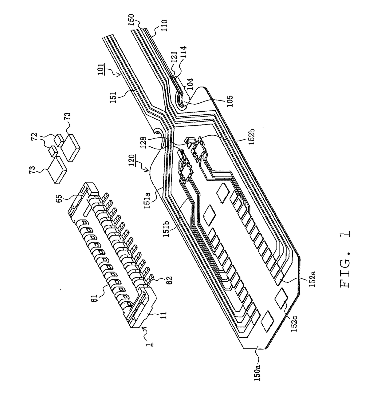
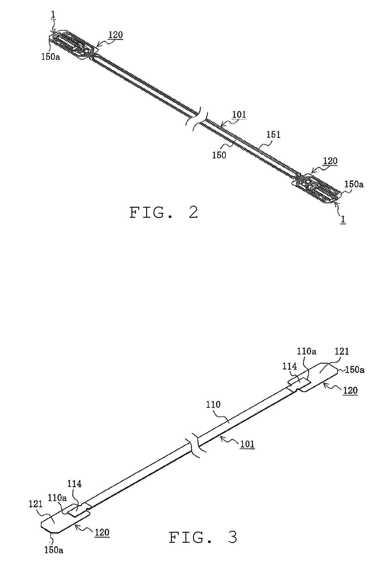
[0010]An object of the Present Disclosure, to resolve the conventional problems described above, is to provide a composite cable with a simple structure, low manufacturing cost and high reliability that can securely bond components on the top surface of a conductive wire part by bonding to the end part of the composite cable having a planar optical waveguide part, including an optical waveguide and having a planar conductive wire part, including a conductive wire by intervening an intermediate plate between the optical and the conductive wire parts.
[0014]According to the Present Disclosure, the composite cable has an intermediate plate intervene between the optical waveguide part and the conductive wire part at the end parts of the composite cable having a planar optical waveguide part that includes an optical waveguide and having a planar conductive wire part that includes a conductive wire. By this, a component can be securely bonded by ultrasonic bonding to the top surface of the conductive wire part while also simplifying the structure, suppressing manufacturing cost, and improving reliability.

Problems solved by technology

In recent years, although high speed signal transmission is required for high definition images and the like, the restriction on the internal size of the hinge has made equipping a wide or large diameter conductive wire difficult.
Further, when considering grounding measures to control electromagnetic interference (EMI), the width of the conductive wire becomes even larger.
However, with the conventional cable 901, because the flexible optical waveguide film 910 and the conductive film 950 are layered via a pliable adhesive layer 941, the flexibility is high, making it difficult to electrically connect the components such as an IC chip, chip condenser and the like to the conductive wire 951.

Method used


Image

  • Composite cable
  • Composite cable
  • Composite cable

Examples


Embodiment Construction

[0025]While the Present Disclosure may be susceptible to embodiment in different forms, there is shown in the Figures, and will be described herein in detail, specific embodiments, with the understanding that the disclosure is to be considered an exemplification of the principles of the Present Disclosure, and is not intended to limit the Present Disclosure to that as illustrated.

[0026]As such, references to a feature or aspect are intended to describe a feature or aspect of an example of the Present Disclosure, not to imply that every embodiment thereof must have the described feature or aspect. Furthermore, it should be noted that the description illustrates a number of features. While certain features have been combined together to illustrate potential system designs, those features may also be used in other combinations not expressly disclosed. Thus, the depicted combinations are not intended to be limiting, unless otherwise noted.

[0027]In the embodiments illustrated in the Figu...


PUM

PropertyMeasurementUnit
conductiveaaaaaaaaaa
rigidityaaaaaaaaaa
areaaaaaaaaaaa

Abstract

A planar optical waveguide part that includes an optical waveguide, a planar conductive wire part that includes a conductive wire, and a connecting end part formed on the lengthwise direction end part, wherein the connecting end part is provided with an optical waveguide end part formed on the lengthwise direction end part of the conductive wire part, a conductive end part formed on the lengthwise direction end part of the conductive wire part, and an intermediate plate intervening between the optical waveguide end part and the conductive end part; the optical waveguide end part, conductive end part, and intermediate plate are bonded by layering; and a bonding pad where components are bonded is formed by ultrasonic bonding to the top surface of the conductive end part.

Description

REFERENCE TO RELATED APPLICATIONS[0001]The Present Disclosure claims priority to Japanese Patent Application No. 2011-049905, entitled “Composite Cable,” filed on 8 Mar. 2011 with the Japanese Patent Office and PCT Application No. PCT / US2012 / 028229, filed on 8 Mar. 2012. The content of the aforementioned Patent Applications are fully incorporated in their entirety herein.BACKGROUND OF THE PRESENT DISCLOSURE[0002]The Present Disclosure relates, generally, to a composite cable.[0003]The ability to fold a casing, in order to both decrease the size of the overall case while increasing the size of a display, is emerging as a need for conventional electronic equipment. When doing so, a signal is transmitted by equipping a conductive wire, such as a flexible printed circuit (FPC), a narrow line coaxial cable or the like, so that it passes through the inside of a hinge part where a casing and another casing are connected, with the ability to rotate. In recent years, although high speed sign...

Claims


Application Information

Patent Timeline
Patent Type & Authority Patents(United States)
IPC IPC(8): G02B6/42G02B6/43H05K1/18H05K1/02
CPCG02B6/4293G02B6/43H05K1/189H05K1/0274H05K2201/10121
Inventor NISHIKAWA, MASAKOSHIMOTSU, AKIHIRO
Owner MOLEX INC
Features
  • R&D
  • Intellectual Property
  • Life Sciences
  • Materials
  • Tech Scout
  • Unparalleled Data Quality
  • Higher Quality Content
  • 60% Fewer Hallucinations
Learn More