
Satellite-based emission and reception device with high multi-path attenuation rate, repeater and satellite which are equipped with such a device

a multi-path attenuation rate, satellite technology, applied in the direction of radio transmission, electrical equipment, transmission, etc., can solve the problems of reducing the width of the frequency band that can be used for signals, affecting the quality of links, and modifying the gain and variation of delay laws, so as to reduce the dimensioning constraints of repeaters, minimize the guard band, and high multi-path attenuation rate

Active Publication Date: 2017-04-04
THALES SA
View PDF5 Cites 1 Cited by
  • Summary
  • Abstract
  • Description
  • Claims
  • Application Information

AI Technical Summary

Benefits of technology

The aim of this invention is to improve satellite-based devices by reducing multi-path attenuation and increasing the separation between adjacent channels. This will minimize the need for repeaters and reduce the size and weight of equipment.

Problems solved by technology

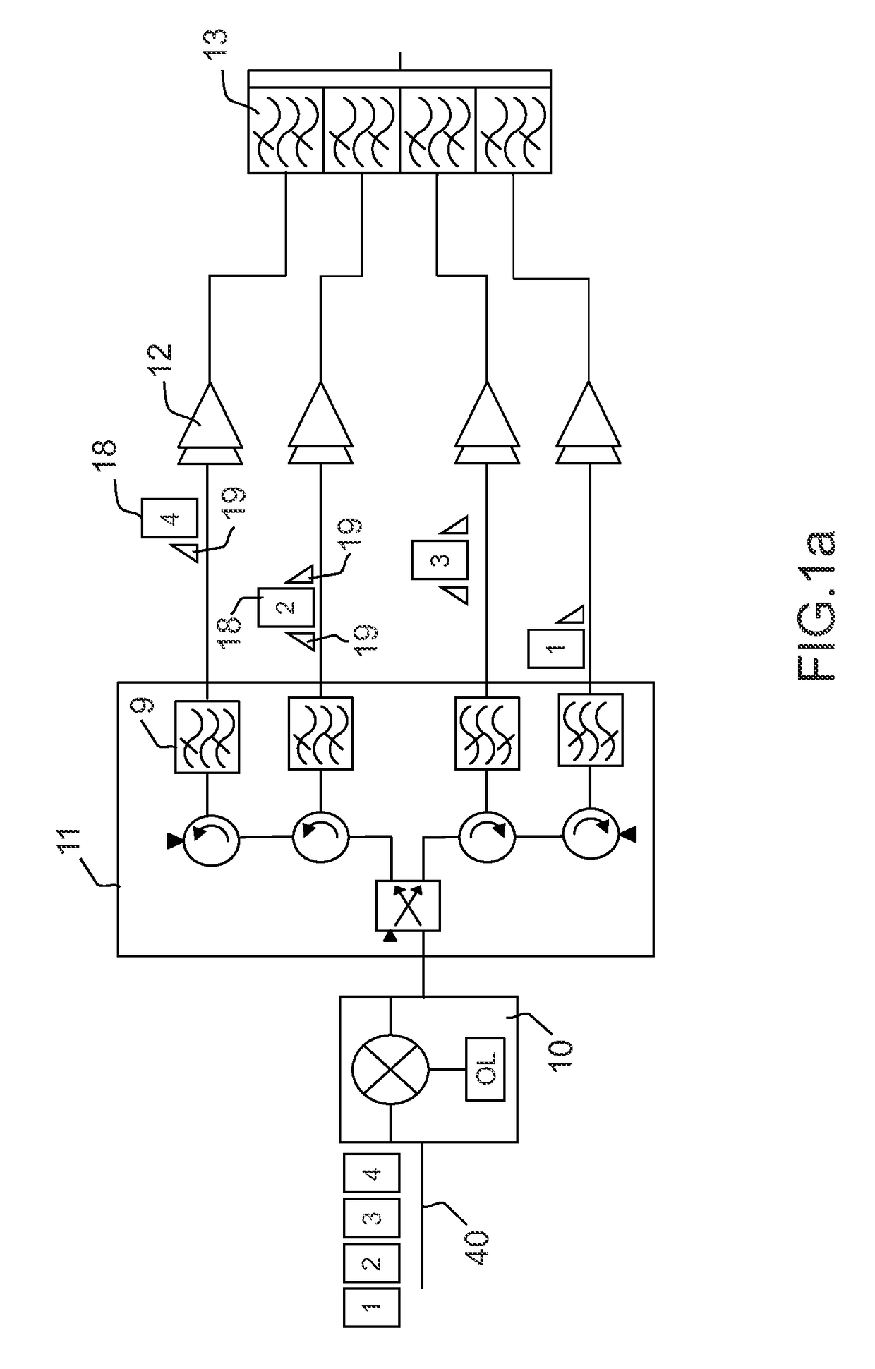
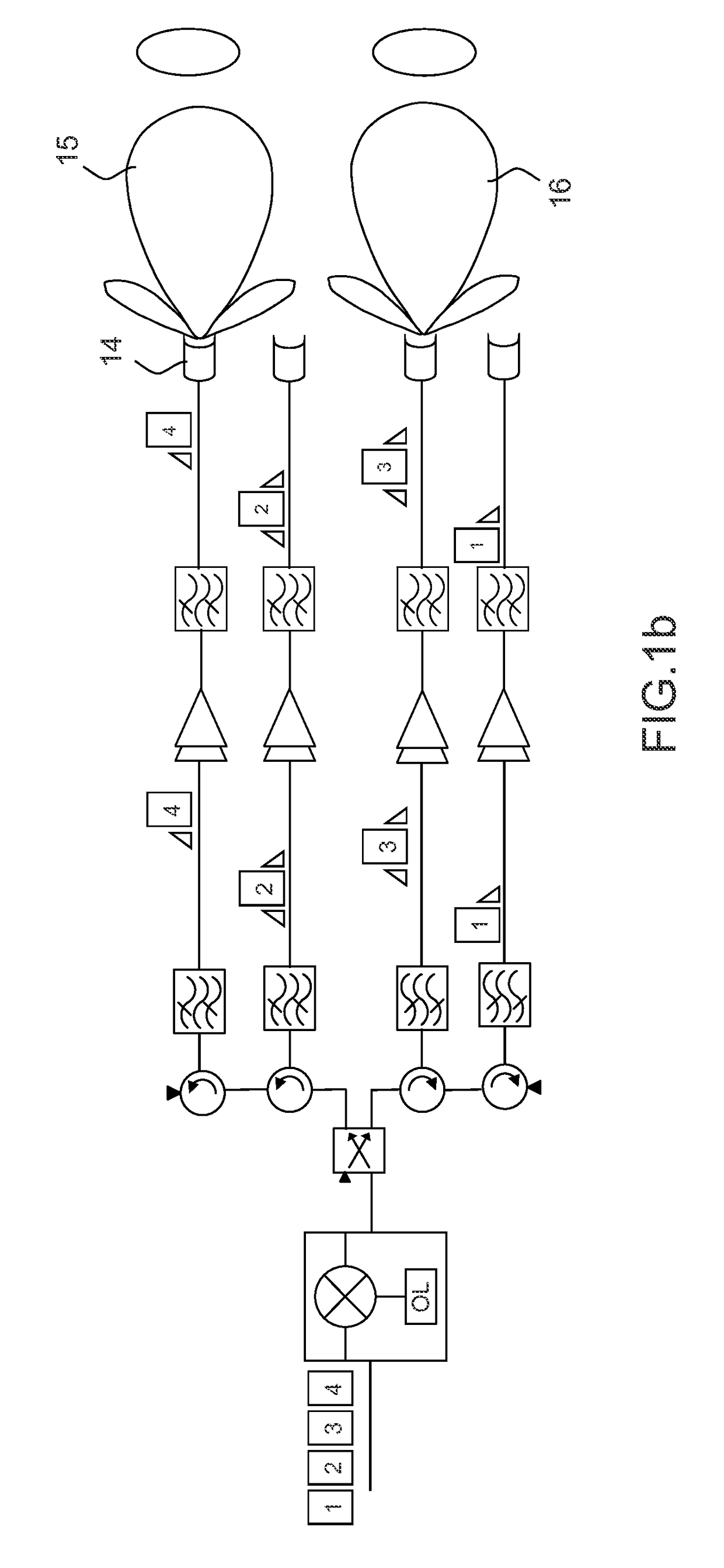
These two architectures exhibit a significant problem due to the fact that the filters 9 of the input demultiplexer 11 which ensure the filtering of the various frequency sub-bands 1 to 4 are not perfect and allow through, in each channel, spurious frequencies belonging to the sub-bands allotted to the adjacent channels.
During recombination of the signals arising from the various channels, in the output multiplexer or by radiation, the main signals and the spurious signals of the same frequency arising from adjacent channels then recombine with one another in a coherent manner, thereby modifying the gain and the variation of the delay law and impairing the quality of the link.
However, this solution exhibits the drawback of decreasing the width of the frequency band that can be used for the signals to be transmitted.

Method used


Image

  • Satellite-based emission and reception device with high multi-path attenuation rate, repeater and satellite which are equipped with such a device
  • Satellite-based emission and reception device with high multi-path attenuation rate, repeater and satellite which are equipped with such a device
  • Satellite-based emission and reception device with high multi-path attenuation rate, repeater and satellite which are equipped with such a device

Examples


Embodiment Construction

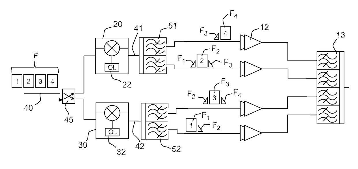
[0015]In FIGS. 2a and 2b, in accordance with the invention, the repeater emission and reception system comprises a power divider 45 intended to divide the power of a radiofrequency input signal 40 by two and to apply the two signals arising from the division, respectively as input to two independent frequency converters 20, 30. Each frequency converter 20, 30 is intended to receive and to process in parallel the radiofrequency signals 40, with broad frequency band F, originating from one and the same uplink. The two frequency converters 20, 30 each comprise a local oscillator 22, 32 and can comprise furthermore a low noise input amplifier and an output amplifier, neither represented. Each frequency converter 20, 30 ensures the transposition of the broad frequency band signals 40 received, from the reception frequency band to the emission frequency band dedicated to the users. The local oscillators 22, 32 of the two frequency converters 20, 30 operate on one and the same frequency, t...


PUM


Abstract

A satellite-based emission and reception device, intended to receive and to process radiofrequency signals originating from an uplink and then to emit the processed signals on a downlink towards terrestrial users, comprises a power divider, two independent frequency converters and two input demultiplexers connected respectively at the output of the two corresponding frequency converters, each frequency converter being controlled by a dedicated local oscillator, the two local oscillators operating at one and the same frequency, the two input demultiplexers comprising channel filters operating in different, disjoint frequency sub-bands spaced apart in frequency, two adjacent frequency sub-bands being filtered by two channel filters belonging to different input demultiplexers.

Description

CROSS-REFERENCE TO RELATED APPLICATION[0001]This application claims priority to foreign French patent application No. FR 1302692, filed on Nov. 22, 2013, the disclosure of which is incorporated by reference in its entirety.FIELD OF THE INVENTION[0002]The present invention relates to a satellite-based emission and reception device with high multi-path attenuation rate, a repeater and a satellite which are equipped with such a device. It applies particularly to the field of satellite telecommunications.BACKGROUND[0003]The repeaters mounted aboard known communication satellites comprise emission and reception systems which rely on transparent architectures offering uplinks between at least one terrestrial station and the repeater and downlinks between the repeater and a plurality of users. The emission and reception systems can cover a terrestrial geographical zone of coverage by means of a lone beam forming a single ground spot or by means of several beams forming multiple ground spot...

Claims


Application Information

Patent Timeline
Patent Type & Authority Patents(United States)
IPC IPC(8): H04B7/185H04B1/00
CPCH04B7/18515H04B1/0057H04B1/38H04B7/185
Inventor MAILLET, OLIVIERMAFFERT, ADRIENCACHERA, RUDYCARTIER, NICOLAS
Owner THALES SA
Learn More