
Vehicle electrical distribution system stabilization

a technology for electrical distribution systems and vehicles, applied in the direction of electric vehicles, three-or-more-wire dc circuits, electric devices, etc., can solve the problems of known transfer devices responding too slowly, affecting the stability of the vehicle electrical distribution system, etc., to achieve the effect of improving energy compensation

Active Publication Date: 2017-04-11
DR ING H C F PORSCHE AG
View PDF21 Cites 2 Cited by
  • Summary
  • Abstract
  • Description
  • Claims
  • Application Information

AI Technical Summary

Benefits of technology

[0012]Since the sampling devices are provided locally at the transfer device, a lag time which can elapse up to the determination of the presence of the preconditions for corresponding energy transmission can be short. The voltage of at least one of the vehicle electrical distribution systems can thus also be stabilized in an improved manner under difficult conditions. In particular, it is possible to operate consumers which consume a high level of energy in pulsed fashion. Such consumers can comprise, for example, an electric starter motor, an electric power-assisted steering system or an electric braking device. The transfer device can provide improved energy compensation, which can make it possible to dimension one of the energy stores such that it is weaker. As a result, costs can be saved and a mass and an installation space onboard the motor vehicle can be saved.
[0014]It is preferable that a change in the direction of transfer between the vehicle electrical distribution systems takes place within fewer than 10 ms, further preferably within less than 5 ms, after the beginning of the energy withdrawal. These response times are achievable by the omission of a complex data transmission, in particular on a serial bus, and can ensure improved stabilization of the vehicle electrical distribution system even in the event of short-term loading.
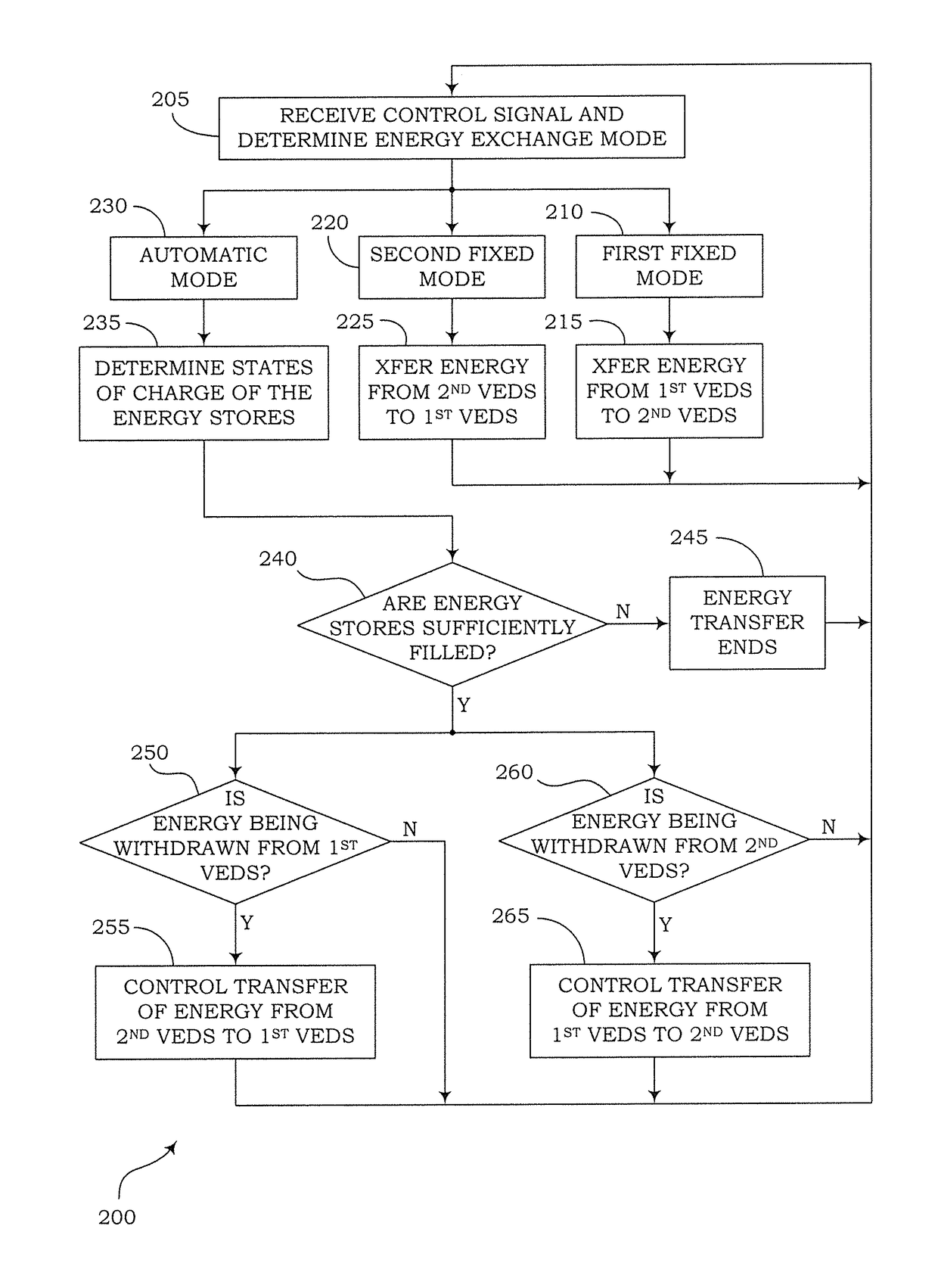
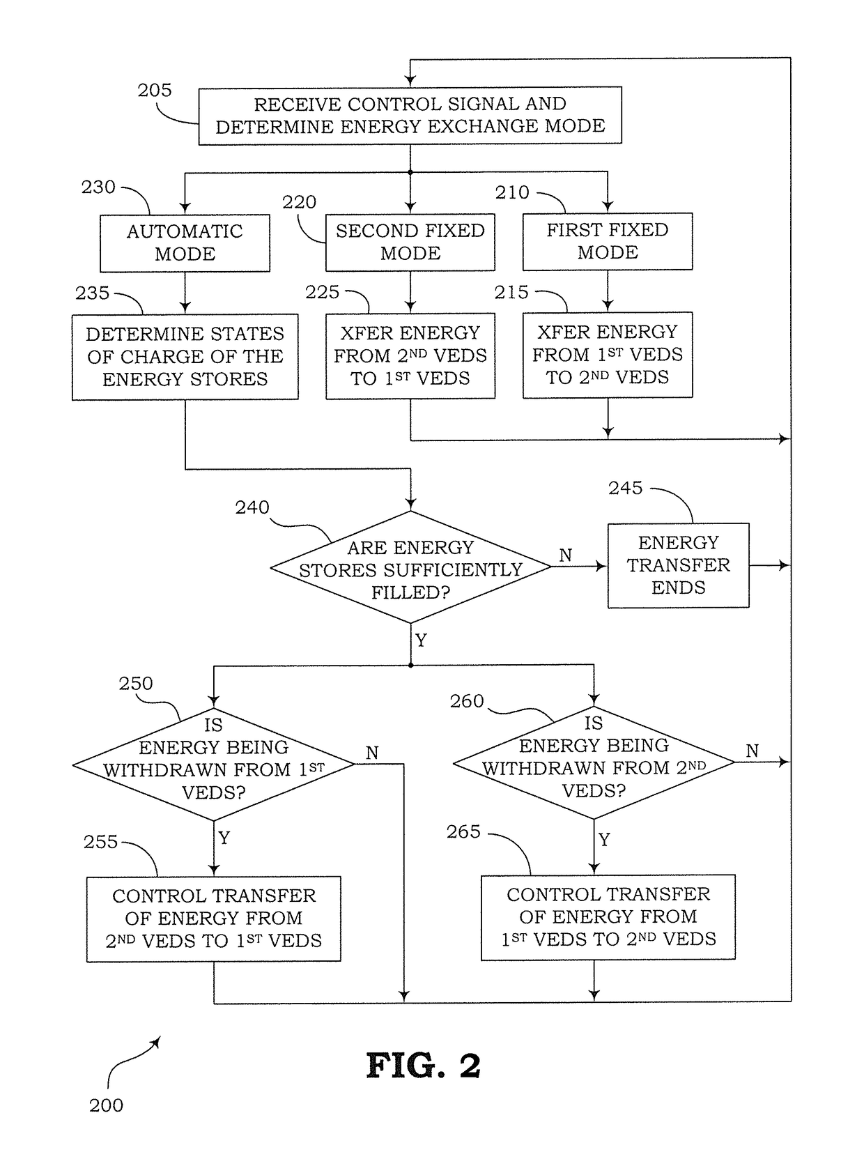
[0015]In one embodiment, the control device is designed to control the transfer of energy between the vehicle electrical distribution systems, as an alternative to the automatic mode, in one of two further modes, wherein in a first fixed mode, energy is transferred from the first vehicle electrical distribution system into the second vehicle electrical distribution system, and in a second fixed mode, energy is transferred from the second vehicle electrical distribution system into the first vehicle electrical distribution system. The mode used can be selected, for example, by means of an external control device. The external control device can activate the mode on the basis of more complex decisions, such as, for example, on the basis of a predictive determination of energy withdrawals. The automatic mode makes it possible to bypass the external control device and implement the decision finding for the direction of an energy transmission locally with increased speed in order to realize short response times.
[0016]In a development of this variant, an interface for receiving a control signal is provided, wherein the control device is designed to implement the control in the automatic mode, in the first fixed mode or in the second fixed mode depending on the received control signal. As a result, in particular improved compatibility with known transfer devices can be provided. This can make it possible to design the transfer device such that, in contrast to a known transfer device, it only controls an additional mode which can be activated if required and otherwise can be replaced by a known transfer device. The transfer device can thus be produced without any further differentiation with respect to the conditions in the motor vehicle in which it is to be installed.
[0018]The method can contribute to providing an improved energy compensation between vehicle electrical distribution systems onboard a motor vehicle, in particular in conjunction with the above-described transfer device.
[0019]In one embodiment, it is detected that the energy store of one of the vehicle electrical distribution systems has been filled sufficiently, for example when a voltage of the associated vehicle electrical distribution system reaches the rated voltage. Advantageously, the determination can thus be performed without an additional sensor being installed or data interchange with a further component outside the transfer device needing to be performed.

Problems solved by technology

For short-term events which can represent a load on one of the vehicle electrical distribution systems in terms of their energy balance, the known transfer devices respond too slowly, however.
Consumers subject to pulses, such as, for example, an electric drive of a power-assisted steering system can thus severely load one of the vehicle electrical distribution systems.

Method used


Image

  • Vehicle electrical distribution system stabilization
  • Vehicle electrical distribution system stabilization
  • Vehicle electrical distribution system stabilization

Examples


Embodiment Construction

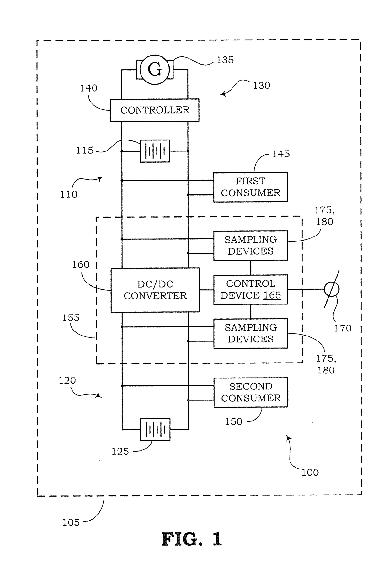
[0025]FIG. 1 shows a system 100 onboard a motor vehicle 105. The system 100 comprises a first vehicle electrical distribution system 110 comprising a first energy store 115 and a second vehicle electrical distribution system 120 comprising a second energy store 125. The vehicle electrical distribution systems 110 and 120 preferably have different rated voltages. In particular, end-of-charge voltages of the energy stores 115 and 125 can be different than one another. This configuration can be selected, for example, when an electric drive or additional drive of the motor vehicle 105 is intended to be fed from the second vehicle electrical distribution system 120, for example. By way of example, it is assumed here that the rated voltage of the first vehicle electrical distribution system 110 is lower than that of the second vehicle electrical distribution system 120. The first vehicle electrical distribution system 110 has, for example, a rated voltage of 12 V, while the second vehicle...


PUM


Abstract

A transfer device for energy in a motor vehicle is designed for connection to a first vehicle electrical distribution system and a second vehicle electrical distribution system, which each comprise an associated energy store. In this case, the transfer device comprises a first sampling device for determining that the two energy stores have been filled sufficiently, a second sampling device for detecting an energy withdrawal from one of the vehicle electrical distribution systems, and a DC-to-DC converter for transferring energy between the vehicle electrical distribution systems. In addition, a control device is provided which is designed, in an automatic mode to control a transfer of energy from one of the vehicle electrical distribution systems into the other vehicle electrical distribution system on the basis of the signals of the sampling devices when energy is withdrawn from the other vehicle electrical distribution system.

Description

CROSS REFERENCE TO RELATED APPLICATION[0001]This application claims priority under 35 USC 119 to German Patent Appl. No. 10 2013 106 777.8 filed on Jun. 28, 2013, the entire disclosure of which is incorporated herein by reference.BACKGROUND[0002]1. Field of the Invention[0003]The invention relates to vehicle electrical distribution system stabilization. In particular, the invention relates to stabilization of two separate vehicle electrical distribution systems onboard a motor vehicle.[0004]2. Description of the Related Art[0005]A motor vehicle comprises a vehicle electrical distribution system which is generally fed by a generator, which is driven by an internal combustion engine for driving the motor vehicle. A second vehicle electrical distribution system which is isolated from the first vehicle electrical distribution system can be provided, for example when the motor vehicle has an additional electrical drive. The two vehicle electrical distribution systems generally have diffe...

Claims


Application Information

Patent Timeline
Patent Type & Authority Patents(United States)
IPC IPC(8): H02G3/00H02J1/08F02N11/08B60R16/033B60L3/00H02J7/14B60L1/00H02J1/00
CPCB60R16/033F02N11/0866H02J1/08H02J7/14H02J2001/008H02J1/082H02J2310/46
Inventor REBHOLZ, HEINZKEHL, STEFFEN
Owner DR ING H C F PORSCHE AG
Learn More