Radio communication apparatus, radio communication method, and radio communication system

a radio communication system and radio communication technology, applied in the field of radio communication apparatus, radio communication method and radio communication system, can solve the problems of failure of radio communication, no protection of propagation path, and inability to perform communications

Active Publication Date: 2017-04-11
KOKUSA ELECTRIC CO LTD
View PDF13 Cites 12 Cited by
  • Summary
  • Abstract
  • Description
  • Claims
  • Application Information

AI Technical Summary

Benefits of technology

[0028]In accordance with the embodiments of the present invention, by browsing the reference image data and the captured image data, it is possible to provide a radio communication apparatus capable of estimating the cause of the failure of the radio communications during the operation, or finding out whether the radio wave condition is expected to become worse afterwards or not.

Problems solved by technology

However, even if it was appropriate when installing the radio communication system, a failure may occur in the radio communications due to various factors as the system continuously operates for a long time.
Accordingly, there is no protection of a propagation path by law, and the communications may not be performed due to an obstacle in the propagation path.
In addition, since there is directivity of the carriers in the millimeter wave band and the quasi-millimeter wave band, in rare cases, the direction may be shifted due to strong wind and an impact, which is resulted in a failure of the radio communications.
Thus, in order to discover the true cause of the failure such as construction of the building, there is a problem that it is necessary for an operator to go to the installation location of the radio communication device and perform a checking operation.
Therefore, in the case where the radio device is installed in a distant area or place where the operator cannot easily access, it takes time to identify and recover the failure.
Thus, it was impossible to estimate the cause of the failure of the radio communications during the operation, or know whether the radio wave condition is likely to become worse afterwards.

Method used


Image

  • Radio communication apparatus, radio communication method, and radio communication system
  • Radio communication apparatus, radio communication method, and radio communication system
  • Radio communication apparatus, radio communication method, and radio communication system

Examples


Embodiment Construction

Control Configuration of a Radio Communication System X

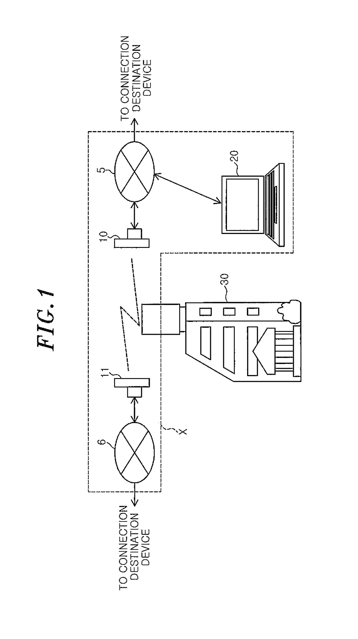
[0035]First, a configuration example of a radio communication system X in accordance with an embodiment of the present invention will be described with reference to FIG. 1.

[0036]In the radio communication system X, radio communication apparatuses 10 and 11 (communication means between bases) perform opposing communications as master and slave apparatuses. The radio communication apparatus 10 and 11 are wirelessly connected to networks 5 and 6 that are external networks. Further, in the radio communication system X, a maintenance device 20 (data analyzing means) is also connected to the network 5 or the network 6.

[0037]For example, the network 5 (or 6) is an IP network of an optical fiber, a LAN network such as 1000BASE-T, a dedicated line or the like. The network 5 (or 6) may be connected to a connection destination device such as a hub, router, PC (Personal Computer), server, smart phone, tablet computer and the like.

[0038]Furt...


PUM


Abstract

A radio communication apparatus includes a radio transmitting / receiving unit having a directional antenna and a storage unit storing reference image data and captured image data obtained by an imaging unit. The imaging unit has an optical axis oriented in the same direction as the radio wave direction of the directional antenna and captures an image related to a line of sight of the other opposed radio communication apparatus. The radio communication apparatus further includes an image processing unit comparing the reference image data with the captured image data and a control unit detecting, from the comparison result, and informing that an obstacle is traveling toward the aforementioned radio wave direction.

Description

FIELD OF THE INVENTION[0001]The present invention relates to a radio communication apparatus, a radio communication method and a radio communication system, and particularly to a P-to-P digital radio communication apparatus, a radio communication method and a radio communication system using a directional antenna.BACKGROUND OF THE INVENTION[0002]In the modern times, a digital radio system has become one of essential techniques due to its reliability and the fact that a radio band can be used efficiently.[0003]In recent years, along with the spread of the Internet, there is an increasing demand for high-speed, large-capacity communications using a wireless medium. Therefore, a radio communication system using a radio communication apparatus such as a radio repeater for P-to-P (point-to-point) connection of LANs (Local Area Networks) of the bases of separate buildings or the like has been developed and put into practical use.[0004]In the radio communication system for P-to-P (point-to...

Claims


Application Information

Patent Timeline
Patent Type & Authority Patents(United States)
IPC IPC(8): G01S13/86H04W24/04G06T11/60H04N5/232H04N7/18
CPCG01S13/867G06T11/60H04N5/23203H04N7/183H04W24/04G06T2207/10004G06T2207/30181H04N23/66
Inventor MURAKAMI, HIROYUKIUJIIE, SATORUSASAKI, KANEMIKOBAYASHI, SHINYA
Owner KOKUSA ELECTRIC CO LTD
Why Eureka
Try Eureka