Optical wiring systems and methods

a technology of optical wiring and data distribution network, applied in the direction of optical elements, coupling device connections, instruments, etc., can solve the problems of expensive waste of wires, waste of water resources, and waste of other resources such as time, which is all too precious to waste, and needs human effort to maintain and be quite often unnecessary

Active Publication Date: 2017-04-11
MURRAY DAVID W
View PDF27 Cites 35 Cited by
  • Summary
  • Abstract
  • Description
  • Claims
  • Application Information

AI Technical Summary

Benefits of technology

[0048]The system will store data indicative of important information and performance history for smart energy adaptations and targeted conveniences. A central timer will reach out for accurate time and send signals to the most accurate time. All smart devices will then have identical time based on the time corresponding to the central device. This central clock simplifies all the other devices and makes uniformity better. Shared sensors in all of the devices will also simplify the number required and add benefits for higher quantity sensing without extra expense. The system's central processing can also make complex associations without having to have expensive processing throughout.
[0053]It is expected that modern systems will be employed to allow utility systems to have external control over certain functions that require a good deal of power consumption. This is to aid in evening out the grid in a manner not requiring ever increasing enhancement that is expensive. To this end the SMART CIRCUIT BREAKER DATA PORT is more organized than the typical circuit breaker box. This enables outside sources some control over some systems during peak cycles. This usually means a lower cost for the owner and can be augmented by using a back-up system to supply the removed amount using solar, back-up generators, or batteries. If battery cost points decrease as expected, whole house back-up systems may become part of the future.

Problems solved by technology

Other resources such as water, time, and human effort are all too precious to waste.
This requires human effort to maintain and is quite often unnecessary.
This is an expensive waste of wire and must be constantly redone to achieve new results.

Method used


Image

  • Optical wiring systems and methods
  • Optical wiring systems and methods
  • Optical wiring systems and methods

Examples


Embodiment Construction

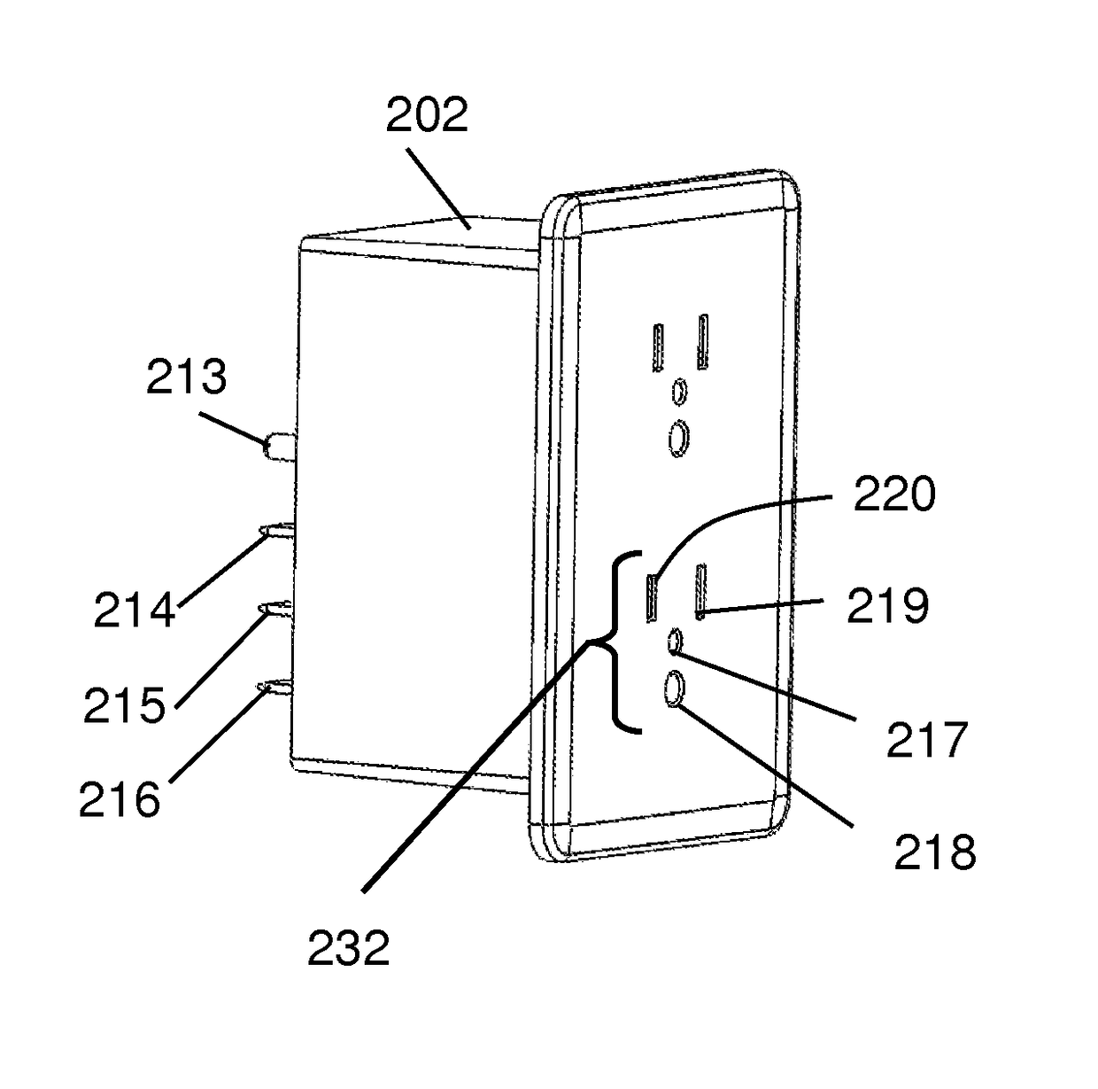
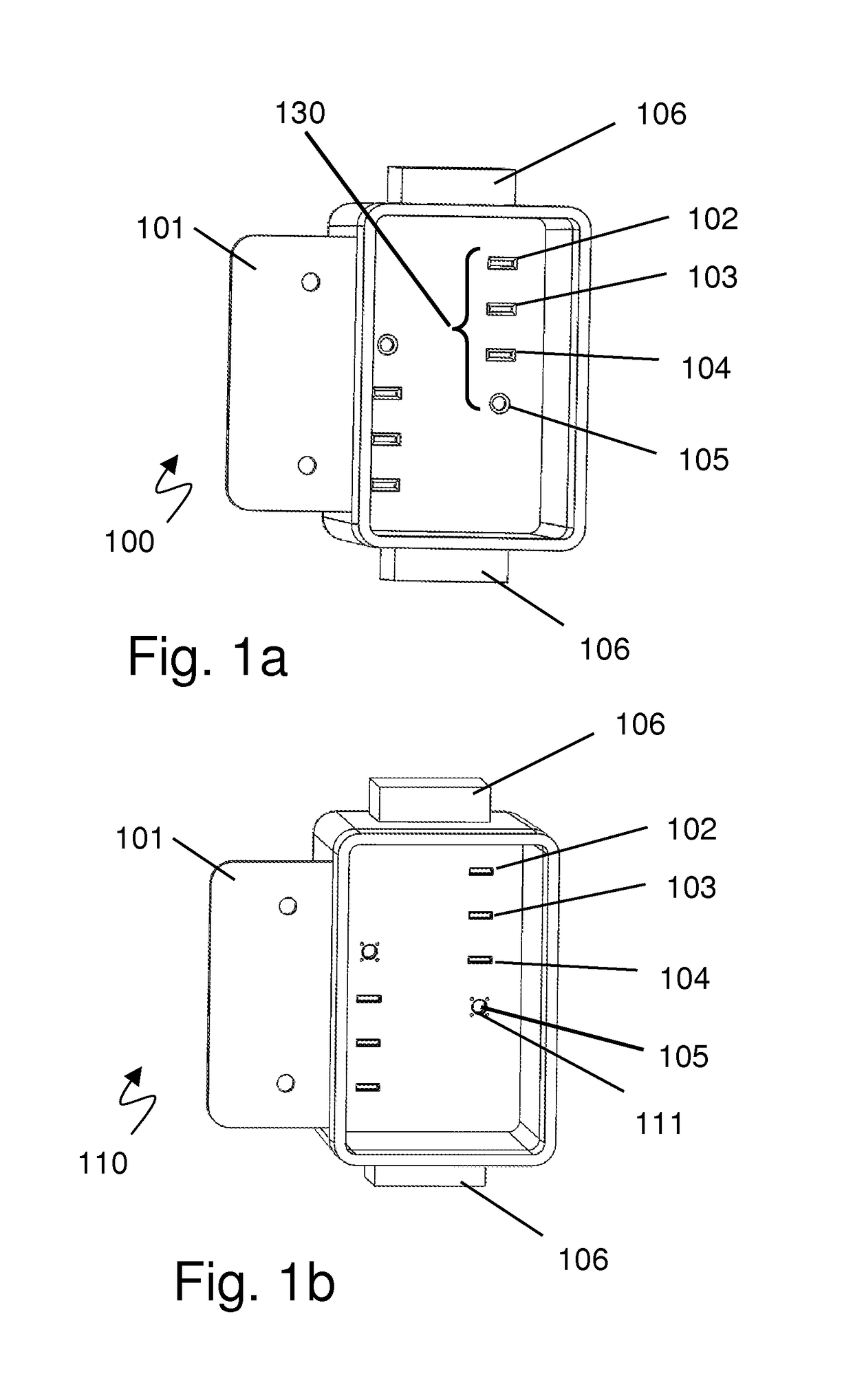
[0124]FIG. 1a illustrates an exemplary termination box for terminating house wiring and interfacing with smart outlets and other devices. FIG. 1a is an isometric view of a termination box 100 showing the basic box 101 with the three wire plus light connections comprising the electrical connectors 102, 103, and 104, and the fiber optic connection 105. The termination box also includes input wiring junctions 106 to connect to building power and optical network. Referring to FIG. 1a, the termination box 100 is part of the backbone of the system. The termination box 100 would be installed similarly to a typical junction box except that all wires and fiber optics are permanently affixed for what is expected to be a very long time. The termination box 100 typically has no active components inside and forms a connection platform for the smart device ports that are plugged into it, which are shown in various Figures in different variations. The power and data are passed from one end 106 to ...


PUM


Abstract

An architected system of distribution of power and information using copper wire for power distribution and fiber optic for communication of information. The architected system is comprehensive for connections and upgrades related to the function, installation, terminations at every junction of a 3 wire plus light system. The archetected system enables each powered device in a smart home, smart office, or smart industrial installation with respect to a permanent and adaptable framework for an network foundation and structure. The architected system may include: wire, connectors, housings, devices, extension cords, appliance termination points, central processing, central power distribution, and a software methods for reliable data distribution.

Description

RELATED APPLICATIONS[0001]This application claims the benefit under 35 USC 119(e) of provisional application Ser. No. 62 / 063,813, titled “Optical Wiring Systems and Methods”, filed Oct. 14, 2014 by Murray, which is hereby incorporated herein by reference in its entirety.BACKGROUND[0002]Technical Field[0003]The present invention pertains generally to the field of optical wiring systems and data distribution networks, more particularly to optical network wiring and connectors in combination with power wiring.[0004]Background[0005]AC and DC powered devices are controlled by interrupting the flow of electricity. For many decades the interruption was manually decided per the action of a person who had a desire to alter function. Many forms of automation have been added over the years to decrease the actions required to achieve a repetitive sequence when certain events occur. A simple switch added to a door allows for light when opened. A motion sensor added to turn on light when a person...

Claims


Application Information

Patent Timeline
Patent Type & Authority Patents(United States)
IPC IPC(8): G02B6/38G02B6/42H01R24/30H01R24/78
CPCG02B6/4278G02B6/3882H01R24/30H01R24/78G02B6/3817G02B6/4293G02B6/4416
Inventor MURRAY, DAVID W.
Owner MURRAY DAVID W
Why Eureka
Try Eureka