

Multi-activity pipe-laying vessel
a multi-activity, pipe-laying technology, applied in the direction of pipe-laying vessels, pipe laying and repair, mechanical equipment, etc., can solve the problems of increasing the cost of the vessel, requiring compromise, and requiring additional length, so as to avoid stoppage and minimise the rotation of the quad joint
- Summary
- Abstract
- Description
- Claims
- Application Information
AI Technical Summary
Benefits of technology
Problems solved by technology
Method used
Image

Examples
Embodiment Construction
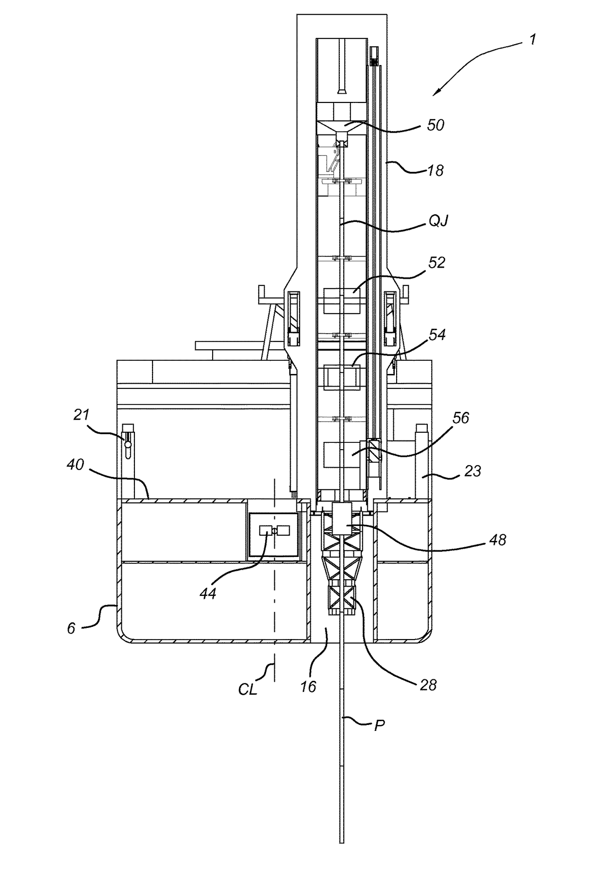
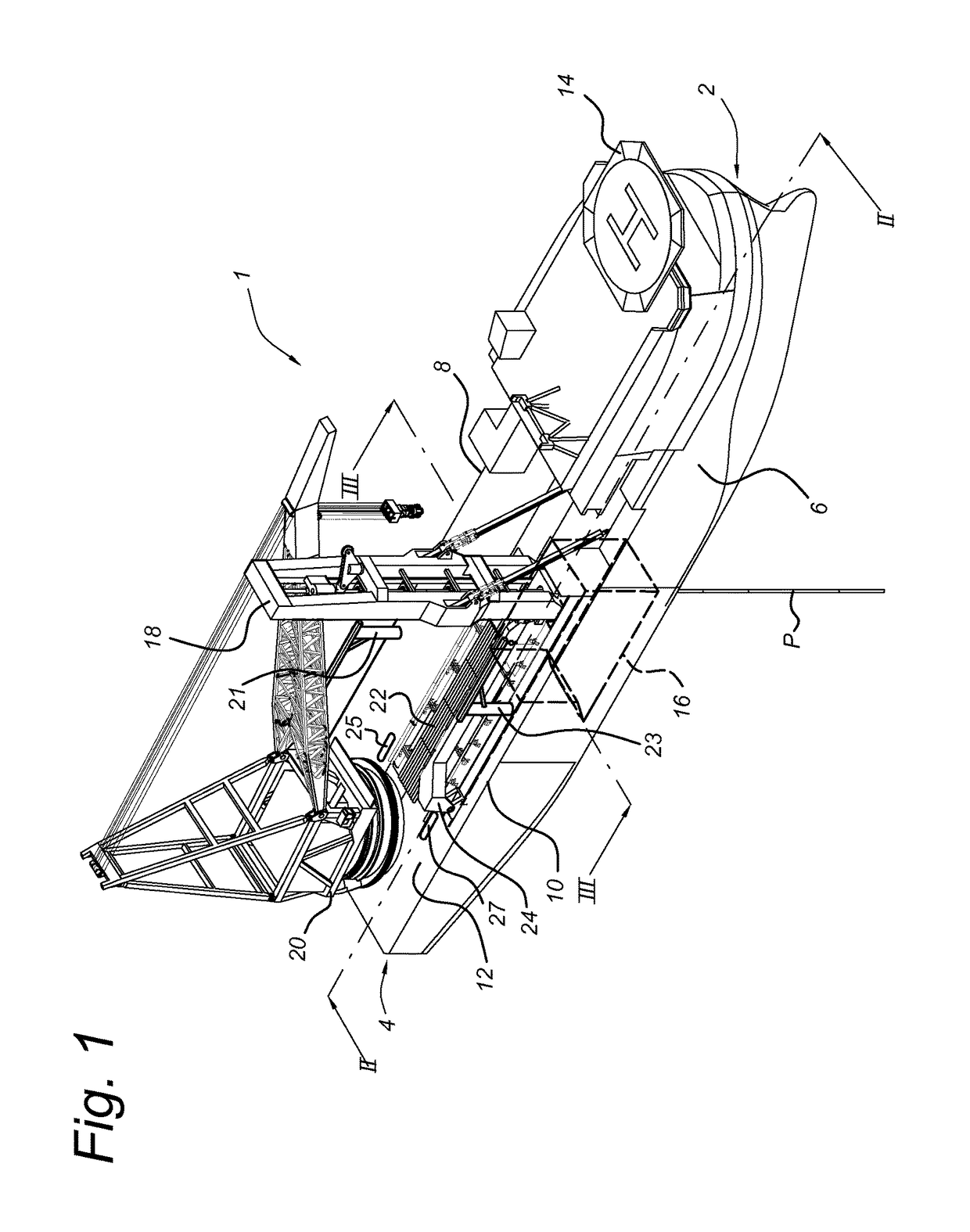
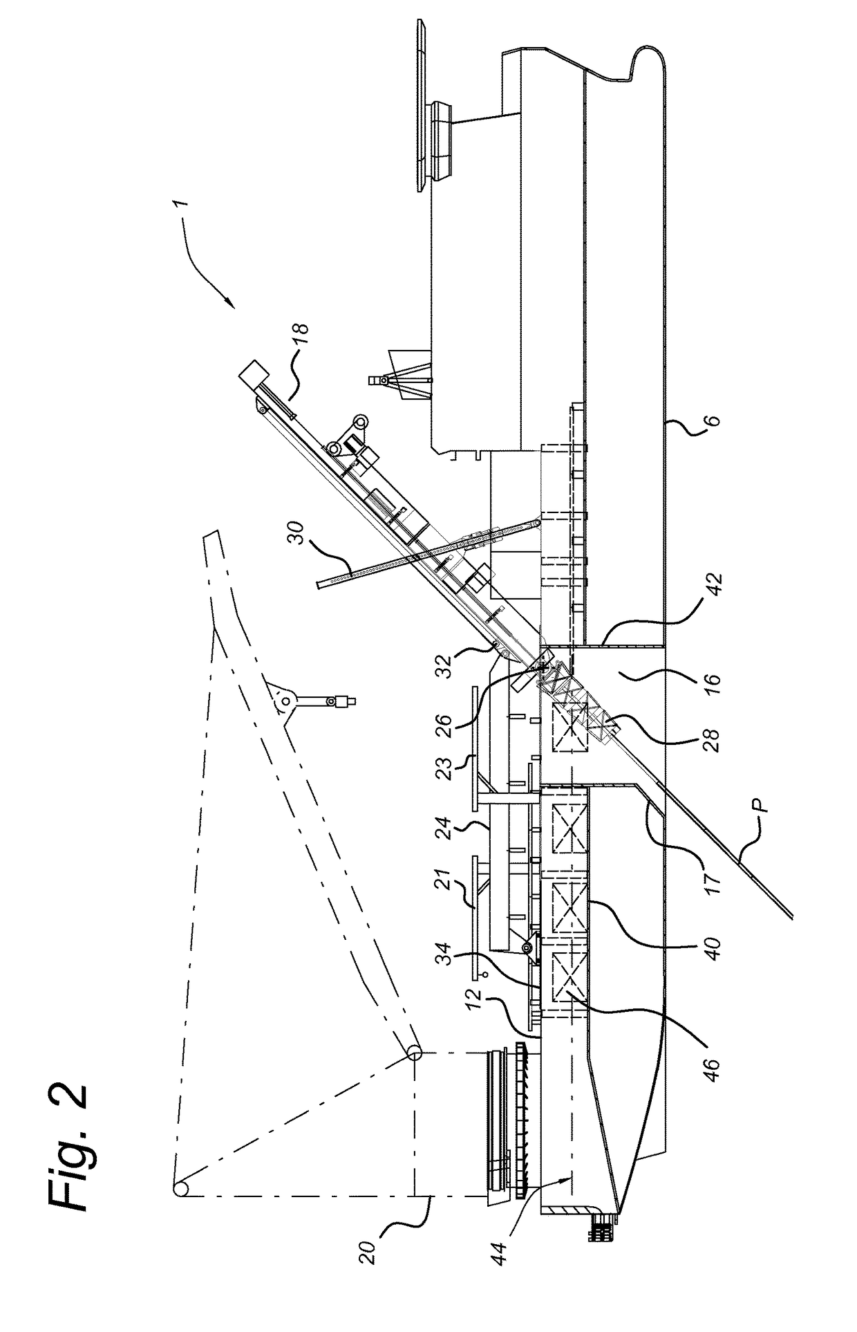
[0034]FIG. 1 shows a perspective view of a pipe-laying vessel 1 according to the invention having a bow 2, a stern 4 and a hull 6 including port and starboard sides 8, 10. The vessel 1 has a number of decks, of which the weather deck 12 and helideck 14 are visible. A moonpool 16 is formed through the weather deck 12 amidships, extending through the hull 6 of the vessel 1. A J-lay tower 18 is depicted located above the moonpool 16, supporting a pipeline P being deployed vertically from the vessel 1 through the moonpool 16 as will be further described in detail below. On the weather deck 12 at the stern 4 of the vessel 1 is located a large tub crane 20. Between the crane 20 and the moonpool 16 is provided a transverse conveyor 22 for quad joints. The J-lay tower 18 carries a loader arm 24, which according to FIG. 1 is in a position over the transverse conveyor 22. A portside loading crane 21 and a starboard loading crane 23 are located amidships, within reach of portside singles hatch...
PUM
 Abstract
Description
Claims
Application Information