Deployable semi-rigid body contact restraint member with integral flexible expansion member

a semi-rigid body and flexible expansion technology, applied in the direction of vehicular safety arrangments, pedestrian/occupant safety arrangements, vehicle components, etc., can solve problems such as inability to achieve easy, and achieve the effect of reducing the likelihood of performance challenges, improving enclosure volume flexibility, and high loading

Active Publication Date: 2017-05-02
FORD GLOBAL TECH LLC
View PDF37 Cites 3 Cited by
  • Summary
  • Abstract
  • Description
  • Claims
  • Application Information

AI Technical Summary

Benefits of technology

[0012]A semi-rigid deployable body contact surface member (or panel) has a first stiffness while an interfacing flexible expansion member has a second, substantially reduced stiffness. The semi-rigid, human body contact surface member is generally stiff and relatively inflexible in a static state (compared to the stiffness of an airbag material), remaining relatively stiff in a dynamic occupant or pedestrian impact condition, distributing load more evenly across the contact surface member (compared to that of an airbag), but capable itself of providing individual assistive energy dissipating deformation in combination with the collective energy management capability of the expandable restraint volume enclosure system to reduce bodily injury upon contact with it.
[0014]Thus, the enhanced load distribution benefit of a semi-rigid deployable body contact surface member is combined with such benefits as increased “throw” distance provided by a more pliable expansion member material capable of withstanding increased internal restraint volume enclosure pressurization for applications where a hybrid restraint performance and pedestrian or occupant body coverage at a greater distance from the packaged restraint device location is needed.
[0016]The above described arrangements withstand high loading, provide substantially improved enclosure volume flexibility, and are expected to reduce the likelihood of performance challenges at extreme temperatures for various future applications. Further, there are various package size, mass, current and future performance and expanded body contact coverage capability advantages achievable through use of alternative flexible expansion member materials. The disclosed inventive concept offers such possible advantages as improved packaging capability reducing the manufacturing, package space and functional constraint associated with the quantity, orientation and shallow depth associated with current semi-rigid bladder-like expansion enclosure volumes.
[0017]Also provided is a more tunable overall deployed shape with expansive capabilities beyond the perimeter of the often panel-like semi-rigid body contact member, providing additional and broader body region contact energy absorption and enabling expansion of asymmetric shapes, providing unilateral or multi-directional, uniform or non-uniform expansion for a variety of future vehicle installations across a vehicle. Potential expandable member weight reduction and faster body contact surface member into position times may also be achievable based on increased flexibility and potentially reduced mass of flexible expansion members, for systems requiring increased restraint volumes and extended body contact member throw distances.

Problems solved by technology

Said otherwise, flexible expansion members are pliable and their pre-packaged position or shape can be displaced readily by hand while displacement of both semi-rigid, often vehicle trim panel-like, body contact surface member and current semi-rigid bladder like expansion members, cannot be achieved easily by hand, instead requiring the force of volumetric chamber expansion to facilitate substantial deformation and displacement.

Method used


Image

  • Deployable semi-rigid body contact restraint member with integral flexible expansion member
  • Deployable semi-rigid body contact restraint member with integral flexible expansion member
  • Deployable semi-rigid body contact restraint member with integral flexible expansion member

Examples


Embodiment Construction

[0046]In the following figures, the same reference numerals will be used to refer to the same components. In the following description, various operating parameters and components are described for different constructed embodiments. These specific parameters and components are included as examples and are not meant to be limiting.

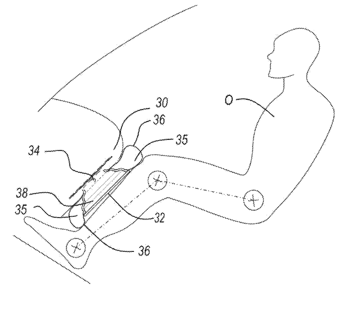
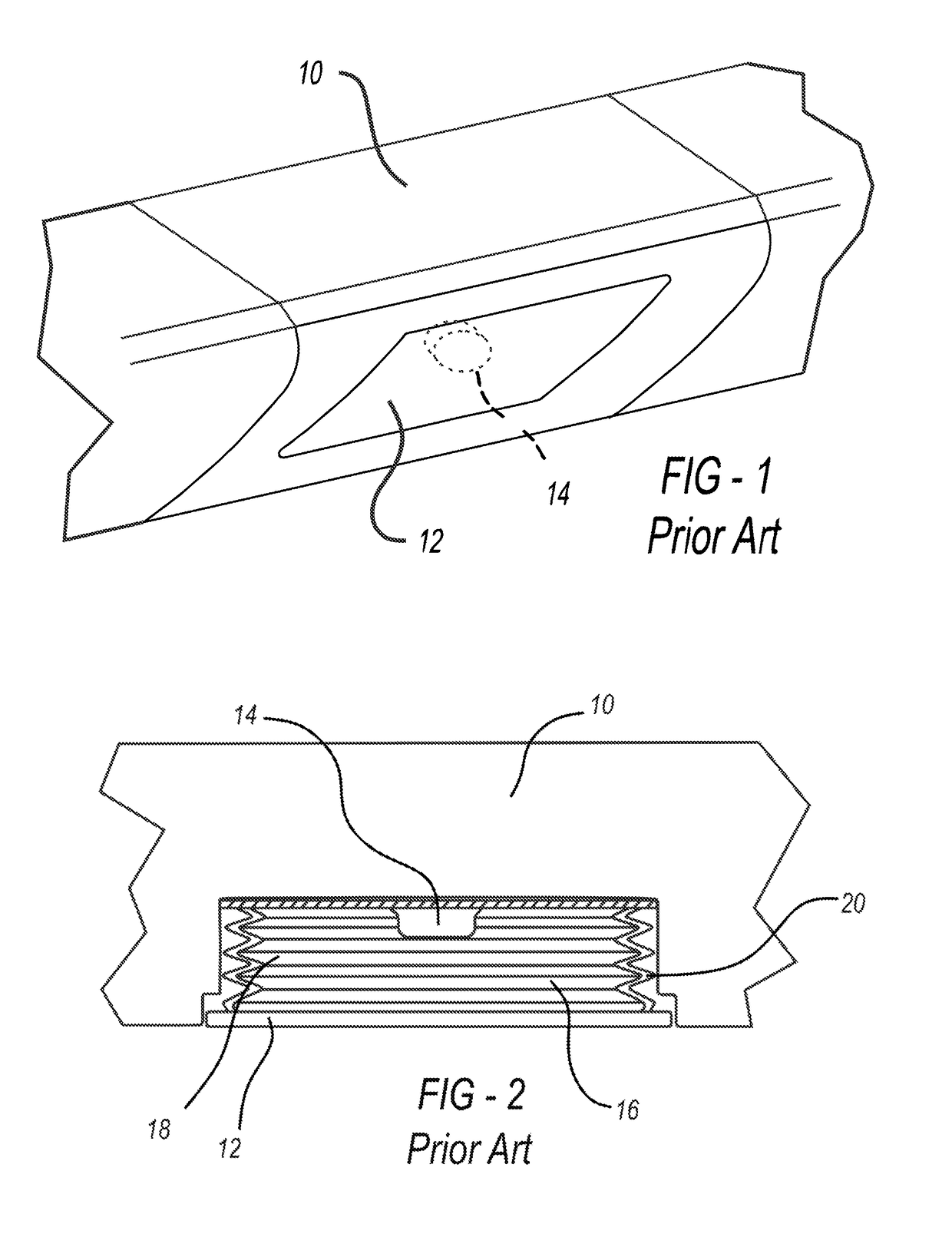
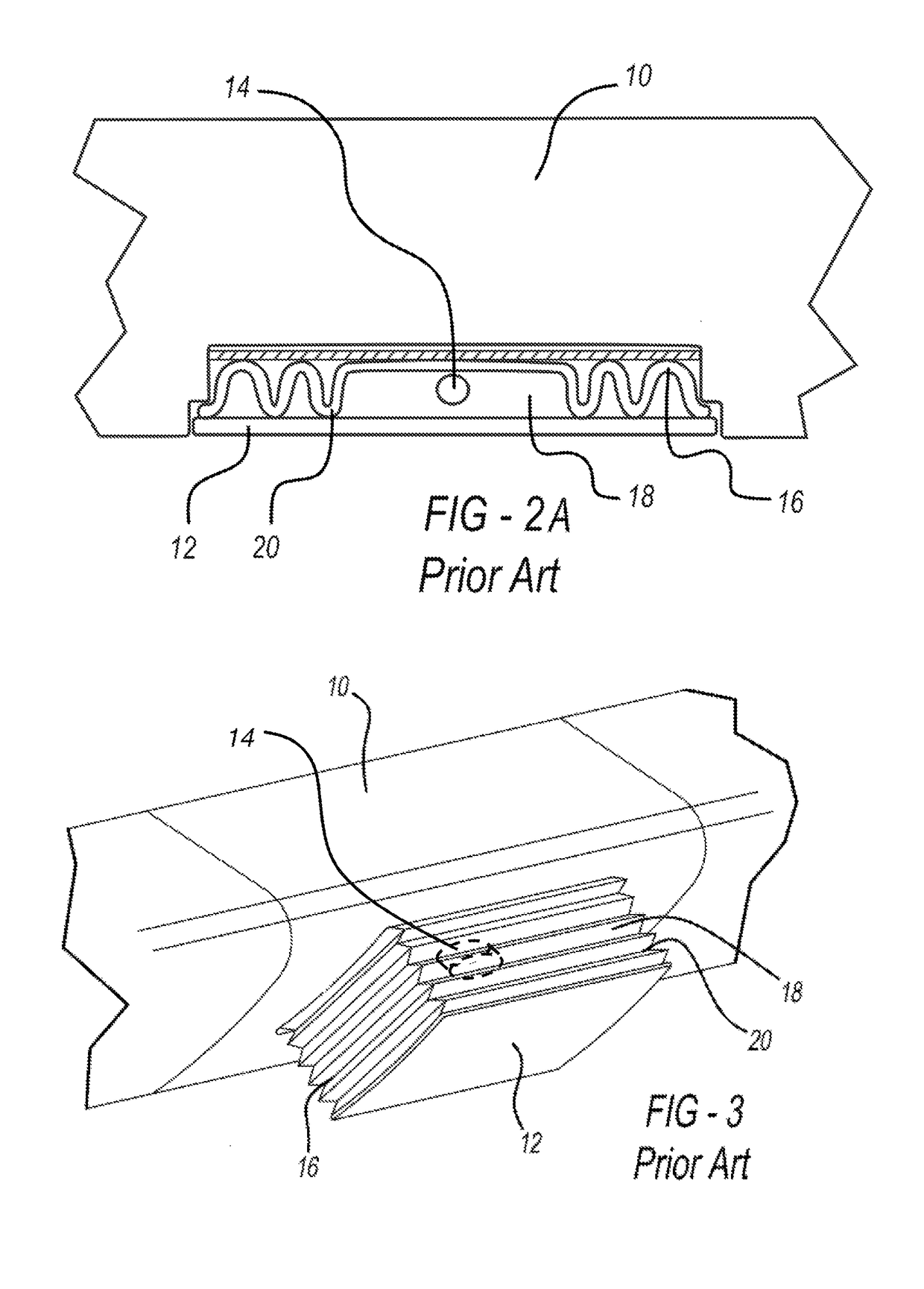
[0047]In general, FIGS. 1 through 4B illustrate a semi-rigid expandable occupant restraint volume enclosure device having a semi-rigid occupant contact surface member interfacing a like material, like-stiffness peripheral bladder-like expansion member positioned within an instrument panel assembly according to the prior art while FIGS. 5 through 18 illustrate a vehicle-mounted hybridized expandable restraint volume enclosure devices incorporating one or more one integrated flexible expansion members interfacing at least one semi-rigid deployable human body contact / reaction surface member according to the disclosed inventive concept.

[0048]FIG. 1 illustrates ...


PUM


Abstract

A hybrid expandable restraint volume enclosure system incorporating at least one deployable semi-rigid human body reaction surface is provided. One or more walls of the expanding volume are substantially pliable, attaching at one end to a mounting base that is attachable to a structural member of a vehicle and another end attached to a semi-rigid deployable reaction surface. The energy absorbing expansion member may be thin walled or membrane-like and comprised of pliable rubber, plastic or a woven fabric. Methods of attaching a flexible expansion member to either a semi-rigid contact surface or a semi-rigid expansion wall of the enclosure include providing a mechanical attachment by capturing an expansion member edge between a frame and semi-rigid member. Material from a molded semi-rigid member may flow over or into geometries provided in a flexible expansion member for joining. An interface may be defined by blend-molding to transition different material stiffness.

Description

TECHNICAL FIELD[0001]The disclosed inventive concept relates generally to vehicle occupant or pedestrian protection systems associated with automotive vehicles. More particularly, the disclosed inventive concept relates to a hybrid expandable restraint volume enclosure device incorporating at least one integrated flexible expansion member having a first stiffness for use in association with a semi-rigid deployable human body contact load dispersion reaction surface member having a relatively increased second stiffness, together provided for the purpose of tailoring the shape and position of a multi-stiffness restraint volume enclosure and reducing injury to a person as the result of a vehicle impact event.BACKGROUND OF THE INVENTION[0002]A variety of safety restraint systems are known for protecting vehicle occupants during an impact event. Seatbelts and airbags are perhaps the most developed and conventional of known safety systems. Known airbags include those which deploy from the...

Claims


Application Information

Patent Timeline
Patent Type & Authority Patents(United States)
IPC IPC(8): B60R21/206B60R21/231B60R21/215B60R21/216B60R21/2338
CPCB60R21/216B60R21/231B60R21/2338B60R21/206B60R21/215B60R2021/2161B60R2021/21512B60R2021/21525B60R2021/23169B60R2021/23382B60R21/16B60R21/21B60R21/235B60R2021/23523
Inventor RUTHINOWSKI, RICHARD EDWARDCHENG, JAMES CHIHBELWAFA, JAMEL E.
Owner FORD GLOBAL TECH LLC
Why Eureka
Try Eureka