Converging cooling system cross section

a cooling system and cross section technology, applied in the field of marine engines, can solve problems such as overcooling of certain parts of the engine, and achieve the effect of reducing the cross sectional area

Active Publication Date: 2017-05-16
BRUNSWICK CORPORATION
View PDF14 Cites 8 Cited by
  • Summary
  • Abstract
  • Description
  • Claims
  • Application Information

AI Technical Summary

Benefits of technology

[0004]U.S. Pat. No. 5,048,467, which issued to Kojima on Sep. 17, 1991, describes a water jacket arrangement for marine two cycle internal combustion engines. An outboard motor having an improved cooling system, wherein liquid coolant is circulated through an exhaust manifold cooling jacket then through a cylinder head cooling jacket and then through an upper portion of the cylinder block cooling jacket, is described. A thermostatic valve controls the flow from the upper cylinder block cooling jacket through a lower cylinder block cooling jacket so as to avoid quenching of the intake charge by coolant which has not reached operating temperature.
[0014]It would be beneficial if a cooling system for a marine engine could remove heat from selected portions of the engine system and avoid the entrapment of air pockets within the coolant flow that could otherwise result in the overheating of local regions of the engine system.
[0020]In another embodiment of the present application, a water jacket for cooling and exhaust manifold that conveys hot exhaust gases from an engine in a marine propulsion system is contemplated. In this embodiment, the water jacket comprises an inlet conduit receiving water from a pump that pumps water from a body of water in which the engine is operating. The water may include entrained air in the form of air pockets or bubbles. The water jacket further comprises an outlet conduit discharging water for cooling the engine and a water flow passage extending from the inlet conduit to the outlet conduit. The water flow passage has a cross sectional area defined by an outer wall, an inner wall, a top wall and a bottom wall. The water flow passage surrounds the exhaust manifold with the water flowing through the passage to cool hot exhaust gases in the exhaust manifold. The water flow passage includes at least one section wherein the outer wall converges with the inner wall to reduce the cross sectional area of the pathway. The water jacket may comprise at least two water flow passage sections wherein the outer wall and inner wall will converge to reduce the cross sectional area along a portion of the pathway. Each water flow passage section may further comprise a first flow portion, a second flow portion, a third flow portion and a fourth flow portion. The inner wall and outer wall of the first flow portion are parallel. In the second flow portion, an outer wall diverges from parallel relative to the inner wall. In the third flow portion, an outer wall and the inner wall converge to parallel. In the fourth flow portion, the inner wall and outer wall are again parallel. The converging flow section of the water jacket reduces the air pockets present in the water to provide even cooling of the exhaust manifold.

Problems solved by technology

The use of cold water can often result in the overcooling of certain portions of the engine and, as a result, the condensing of fuel vapor which can dilute the oil supply of the engine with liquid fuel.
The disadvantages of oil dilution are well known to those skilled in the art of marine engines as are the various types of damage that can result from it.
Other problems associated with cooling marine engines relate to the direction of cooling water as it flows through engine components.

Method used


Image

  • Converging cooling system cross section
  • Converging cooling system cross section
  • Converging cooling system cross section

Examples


Embodiment Construction

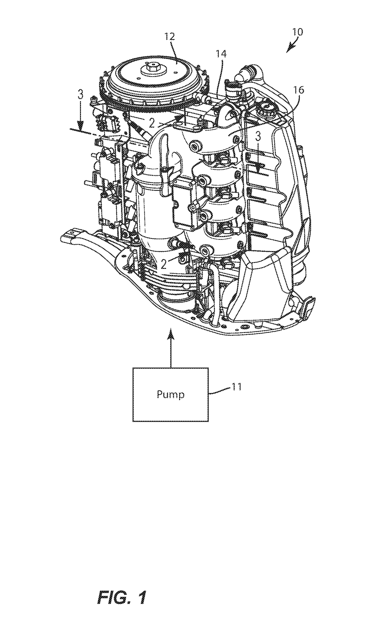
[0025]FIG. 1 demonstrates the conventional engine 10 that includes the system for cooling described herein. The engine 10 may be a marine engine such as an outboard engine, an inboard engine or an inboard / outboard stem drive engine. As one of ordinary skill in the art will readily understand, the invention includes conventional components such as the flywheel 12, engine block 14, and exhaust manifold 16. The system for cooling an engine of a marine propulsion system of the present application focuses on the engine block 14 and exhaust manifold 16.

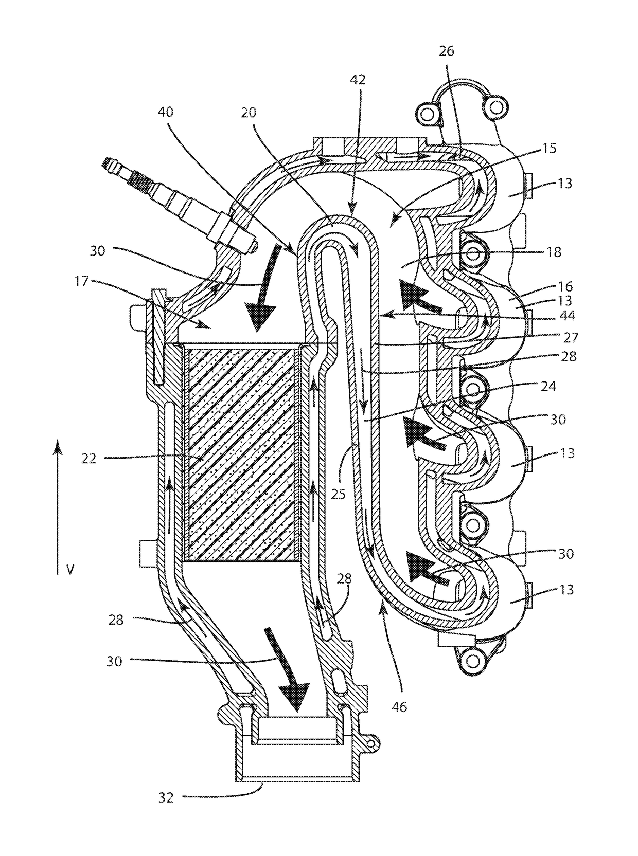
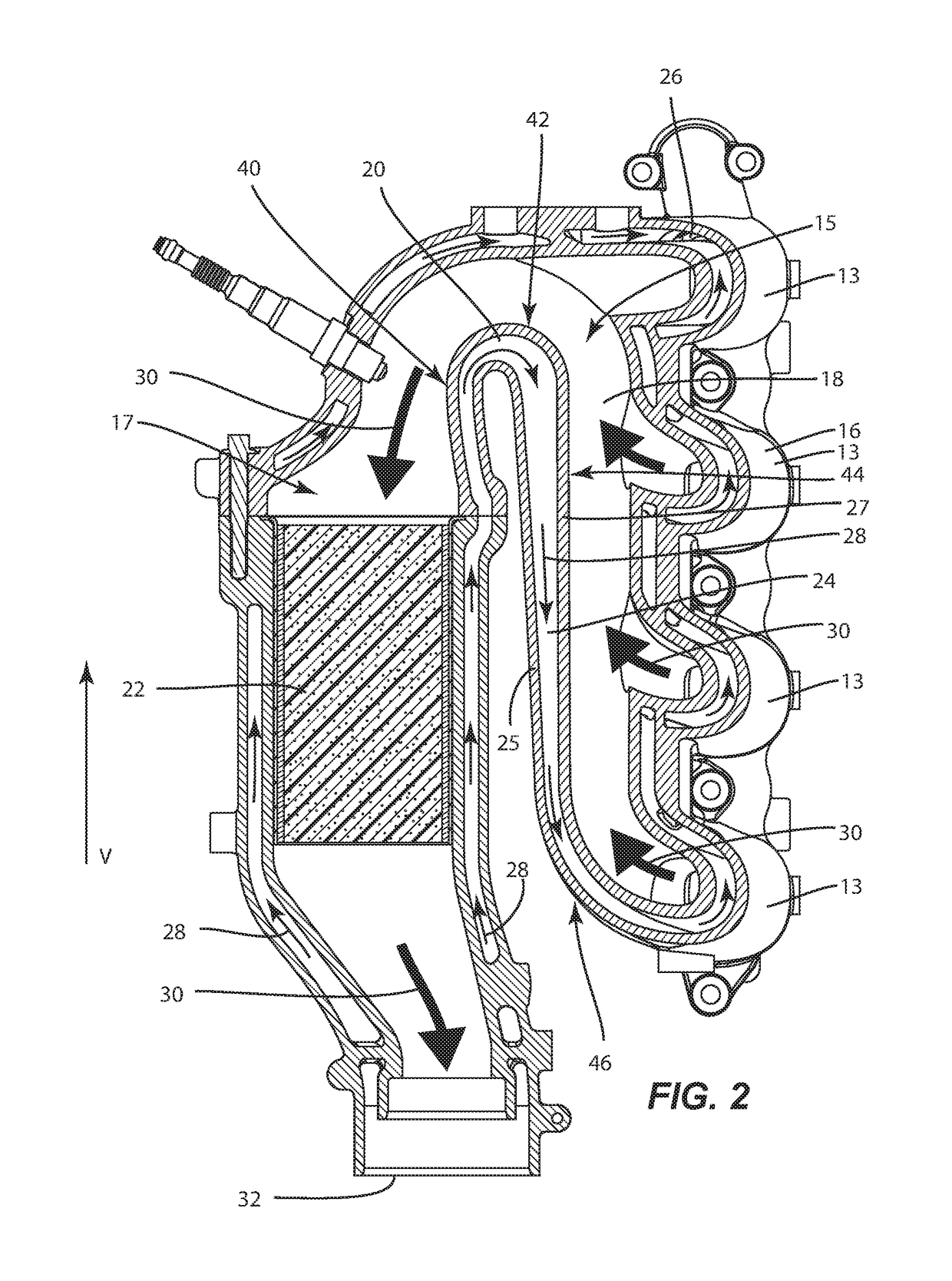
[0026]Turning now to FIG. 2, therein is shown a cross section of the engine 10 along lines 2-2 of FIG. 1. FIG. 3 demonstrates a cross sectional view along line 3-3 of FIG. 1. Turning now to FIGS. 2 and 3, the exhaust manifold 16 includes a plurality of vertically-aligned exhaust runners 13 that are configured to horizontally convey the exhaust gases from the engine 10 and an exhaust passage 18 for expelling exhaust gases from the combustion...


PUM


Abstract

A system for cooling an engine of a marine propulsion system having an engine and having a cylinder block. An exhaust manifold that conveys hot exhaust gases from the engine and a pump that pumps water from a body of water are also present in the system. A water jacket surrounding the exhaust manifold conveys water from the pump along at least one stream of water having a cross sectional area for cooling the hot exhaust gases in the exhaust manifold. At least one portion of the water jacket includes at least one converging passageway including a wall of the water jacket that tapers inwardly to reduce the cross-sectional area of the stream of water as the water circulates in the water jacket. The pumped water typically has entrained air in the form of air pockets. The converging passageway reduces the air pockets present in the water to provide even cooling of the manifold.

Description

FIELD[0001]The present invention is generally related to a marine engine and, more particularly, to an improved water jacket design for cooling a marine engine.BACKGROUND AND SUMMARY[0002]Those skilled in the art of marine engines are familiar with many different types of cooling systems and many different techniques for removing heat from various heat emitting components of marine propulsion systems. Those skilled artisans are also familiar with many important issues associated with the removal of heat from marine engines. Not only is it important to avoid the overheating of various components and devices of a marine propulsion system, but it is also very important to avoid the removal of too much heat from certain portions of the engine. This is particularly true in marine engines, as opposed to engines used to propel land vehicles, because marine engines often use water from a body of water as its primary coolant and the water taken from lakes, rivers, bays, and oceans are often ...

Claims


Application Information

Patent Timeline
Patent Type & Authority Patents(United States)
IPC IPC(8): F01N13/10F01N3/04F01N13/00F01P5/10B63H21/38F01P3/00
CPCF01N13/004F01N3/046F01P3/00F01P5/10B63H21/383F01P2003/001F01N13/10F01N2590/021F01P3/202F01P2060/16Y02T10/12
Inventor GEORGE, TREVORGESSNER, KEITH W.
Owner BRUNSWICK CORPORATION
Why Eureka
Try Eureka