
Cleaning robot

a robot and cleaning technology, applied in the field of robots, can solve the problems of increasing the drag of the vessel hull, increasing the environmental damage of tbt paint, and increasing the build-up of biofouling, so as to reduce the equipment, reduce the drag, and the effect of streamlined operation

Active Publication Date: 2017-05-30
ROLLS ROYCE PLC
View PDF7 Cites 1 Cited by
  • Summary
  • Abstract
  • Description
  • Claims
  • Application Information

AI Technical Summary

Benefits of technology

The patent describes a robot that uses electrical signals to detect areas of surface roughness on a structure and efficiently clean them. The robot can remove microbiological sliming and hard fouling, preventing it from taking hold and damaging the structure. The robot is driven by continuous tracks that reduce contact pressure on the structure. It also has an umbilical that supplies power and controls the robot, and can transmit detector strip electrical signals. The robot can be steered and is not dependant on on-board batteries or generators.

Problems solved by technology

The build-up of biofouling is of concern as it increases vessel hull drag (and associated fuel burn and emissions).
TBT paints have now been shown to be environmentally damaging and are being progressively banned and phased out.
Some “self-polishing” paints contain different biocide compounds, but these are also under increasing environmental scrutiny.
Fouling release paints (FRPs) use a range of low surface energy polymers (sometimes in combination with micro or nano textures) to make it difficult for organisms to attach securely to a vessel's hull.
However, FRPs require fouling to build up to a certain level before it can be shed.
As a result, FRPs incur an increased drag penalty relative to a hull with no fouling.
FRPs also do not address the issue of transportation of invasive species.
However, the process is slow and costly.
Further, poor visibility under water may cause the divers to damage paint or miss areas, resulting in patchy cleaning.
In addition, not all ports allow diver cleaning, as the organisms removed by such cleaning are released and may constitute invasive species.
Most include brushes or scouring pads to remove hard fouling, although such aggressive cleaning approaches can damage paint and initiate corrosion.

Method used


Image

  • Cleaning robot
  • Cleaning robot
  • Cleaning robot

Examples


Embodiment Construction

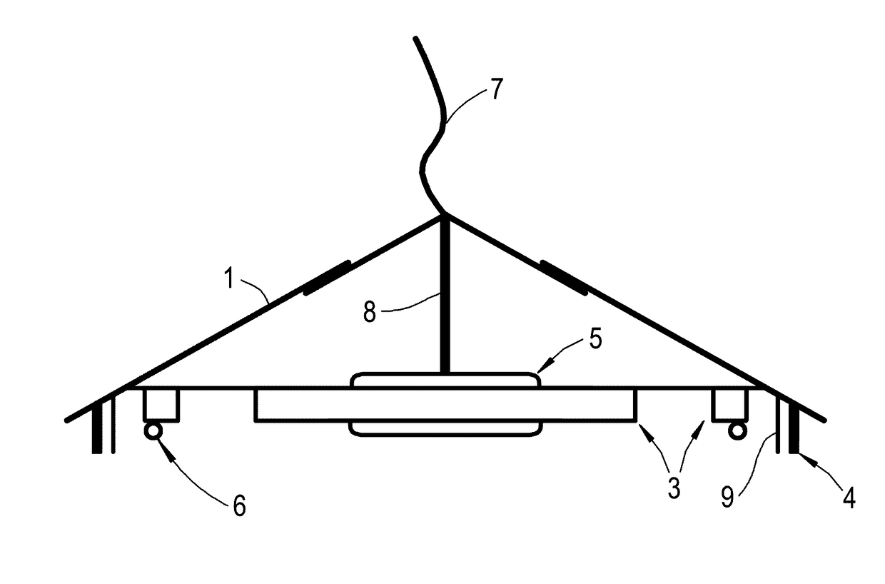
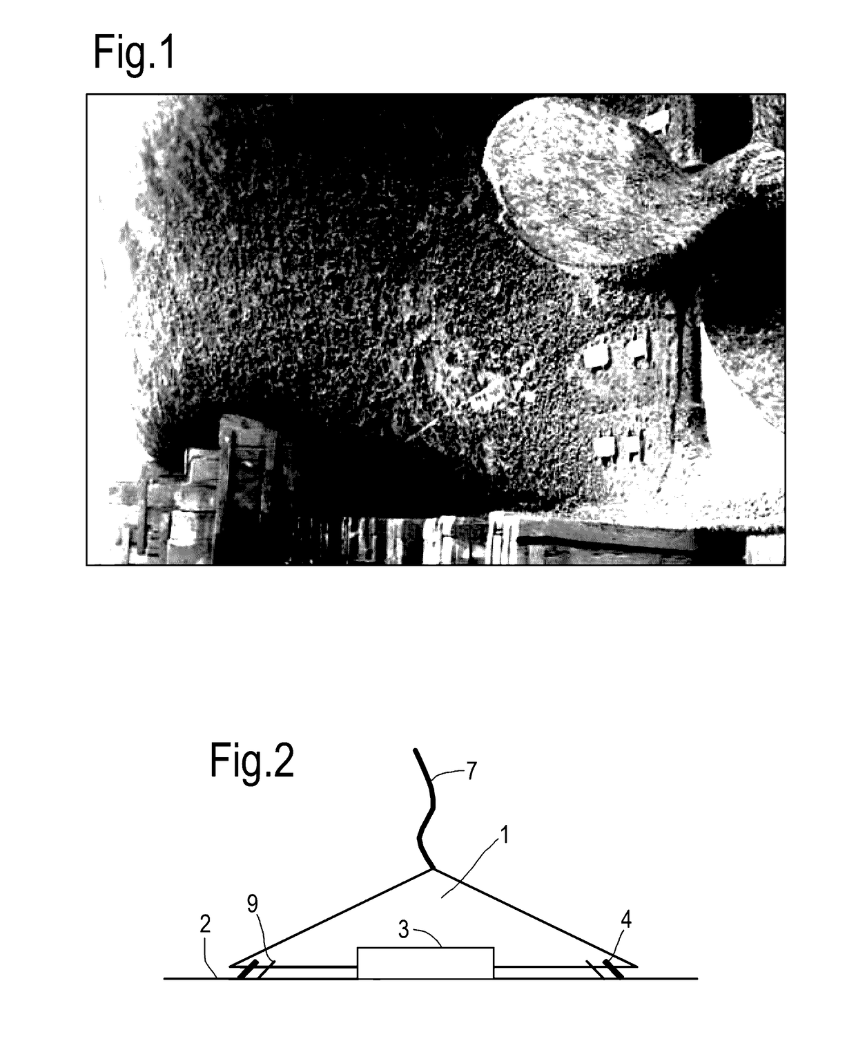
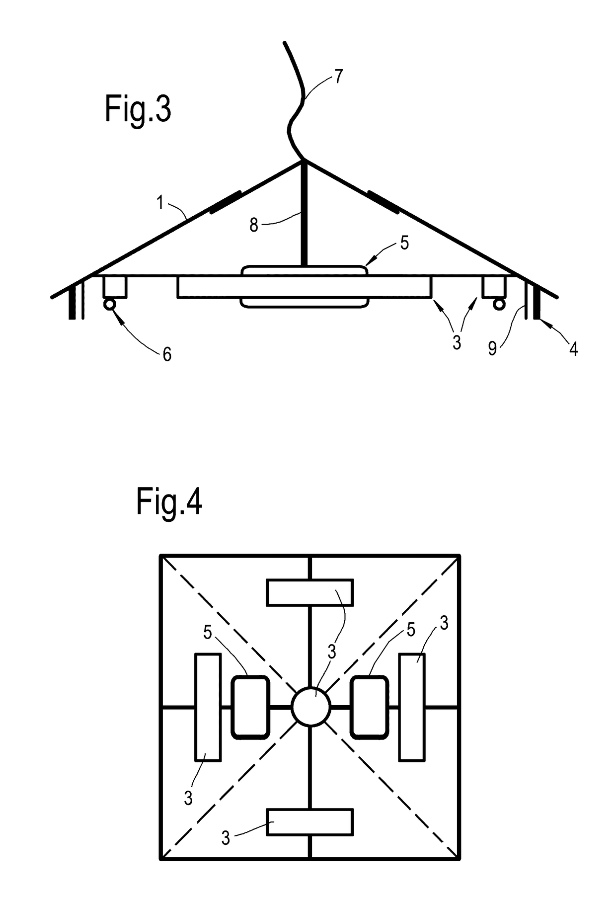
[0045]FIGS. 2 to 4 show schematically side, cross-section and bottom views of a robot according to the present invention. The robot has a housing 1 formed in the shape of a shallow pyramid. The base of the pyramid is located on the surface of the hull 2 of a vessel. Although depicted as a four-sided, square-based pyramid, other base configurations and numbers of sides can be used, or the housing 1 can be conical rather than pyramidal.

[0046]The housing 1 has a small internal angle at its base. This shape reduces drag forces imposed on the robot and allows the robot to be deployed while the vessel is moving, reducing the impact of the robot on the operational profile of the vessel. This approach also allows regular, frequent removal of biofilm from the hull 2, preventing hard-fouling from establishing, and helping to maintain optimum vessel efficiency over long periods of operation.

[0047]For example, the internal angle at the base of the housing can be in the range 5 to 25°, dependant...


PUM


Abstract

A robot for cleaning submersed marine structures is provided. The robot has a drive system for traversing the robot over the submersed structure. The robot further has an attachment system for attaching the robot to the submersed structure. The robot further has a cleaning arrangement for removing biofouling from the submersed structure as the robot is traversed thereover. The robot further has one or more flexible detector strips which contact the submersed structure as the robot is traversed thereover. The strips have a plurality of electrodes and are formed from electroactive polymer material which produces electrical signals in the electrodes on deflection of the strips. The signals are indicative of the surface roughness of the submersed structure.

Description

FIELD OF THE INVENTION[0001]The present invention relates to robot for cleaning submersed marine structures, such as ship's hulls.BACKGROUND OF THE INVENTION[0002]Biofouling is the growth of marine organisms on a structure. Biofouling includes a nucleation stage comprising a microbiological slime, and a subsequent growth stage of hard fouling comprising seaweed, barnacles, limpets, mussels, etc. The build-up of biofouling is of concern as it increases vessel hull drag (and associated fuel burn and emissions). There is also environmental concern about transportion and of release of marine invasive species through shedding of fouling (whether accidently or through cleaning). FIG. 1 shows a ship's hull with heavy hard biofouling.[0003]For many years the control of biofouling on vessels was achieved using biocide paints containing copper compounds or tributyltin (TBT) which kill organisms and spores, preventing attachment and growth of a biofilm. TBT paints have now been shown to be env...

Claims


Application Information

Patent Timeline
Patent Type & Authority Patents(United States)
IPC IPC(8): B08B7/04B63B9/00B63B59/10B08B1/00B63B59/06
CPCB63B59/06B08B7/04B63B9/00B63B59/10B08B1/006B63B71/00B08B1/143
Inventor SIM, ALASTAIRLAMBOURNE, ALEXIS
Owner ROLLS ROYCE PLC
Learn More