
Laundry treating apparatus

a technology for treating apparatus and laundry, which is applied in the direction of other washing machines, sustainable buildings, textiles and papermaking, etc., can solve the problems of unbalanced drum rotation, unbalanced mass distribution of laundry with respect to shaft (rotational axis), and unbalanced state generation, etc., to achieve the effect of improving unbalanced drum rotation

Active Publication Date: 2017-05-30
LG ELECTRONICS INC
View PDF5 Cites 0 Cited by
  • Summary
  • Abstract
  • Description
  • Claims
  • Application Information

AI Technical Summary

Benefits of technology

This solution actively improves drum balance during rotation, effectively reducing vibrations and noise by uniformly distributing liquid to counteract unbalance, improving both diameter and longitudinal plane stability, and addressing the limitations of conventional balancing systems.

Problems solved by technology

According to the location of laundry loaded in the drum, the drum may be unbalanced when rotated (i.e., not keeping a dynamic balance).
Meanwhile, a state where the dynamic balance is lost in a laundry treating apparatus (i.e., an unbalance state) means that mass distribution of laundry with respect to a shaft (rotational axis) is not uniform while a drum is rotated.
The unbalance state may be generated when the laundry is not distributed uniformly.
When the drum rotates in the unbalance state vibration is generated.
The vibration of the drum could be transferred to a tub or a cabinet, such that the transferred vibration might cause a noise problem in the laundry treating apparatus.
However, while the unbalance control system / method mentioned above is effective in a steady state where the vibration of the drum is within a preset range, the unbalance control is expected to be often present in a transient state (i.e., a transient vibration state) before the steady state.
Additionally, it is difficult to immediately improve the unbalance (i.e., to actively ease the unbalance) in the structure of the conventional balancing unit, when the unbalance is generated.

Method used


Image

  • Laundry treating apparatus
  • Laundry treating apparatus
  • Laundry treating apparatus

Examples


Embodiment Construction

[0045]Preferred embodiments of the present invention will be described below in more detail with reference to the accompanying drawings. The present invention may, however, be embodied in different forms and should not be constructed as limited to the embodiments set forth herein.

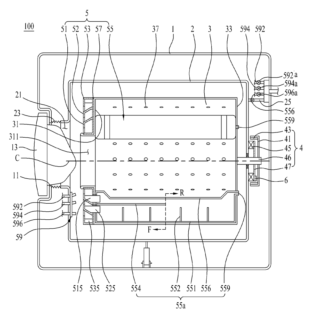
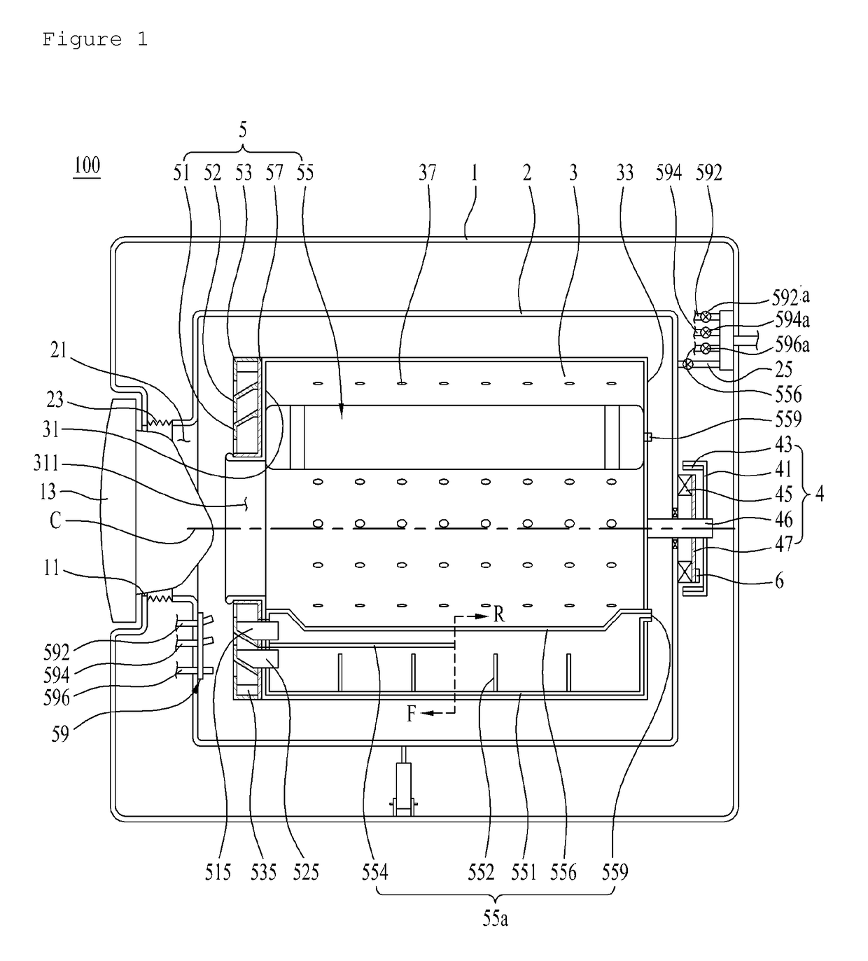
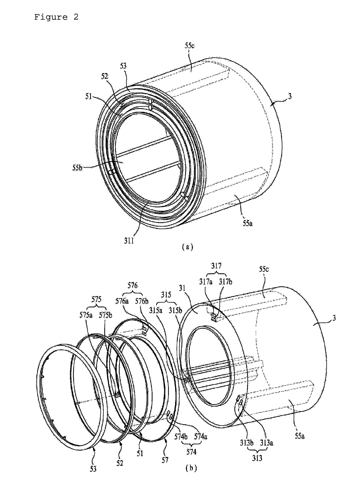
[0046]As shown in FIG. 1, the laundry treating apparatus 100 in accordance with the present disclosure includes a cabinet 1 forming an exterior appearance, a tub 2 provided in the cabinet to hold wash water, a drum 3 rotatably provided in the tub to hold laundry, a driving unit 4 rotating the drum, and a balancing unit 5 controlling unbalance by temporarily increasing the weight of a drum area located opposite where the laundry causing unbalance of the drum is located.

[0047]FIG. 1 illustrates the laundry treating apparatus 100 performing only washing of laundry. If laundry treating apparatus 100 is a laundry treating apparatus performing both washing and drying, an air supply unit (not shown) has to be furt...


PUM


Abstract

A laundry treating apparatus including a cabinet comprising a laundry introduction hole formed therein to introduce laundry, a drum rotatably provided in the cabinet, the drum comprising a drum introduction hole, formed in a front surface thereof, in communication with the laundry introduction hole, at least three main balancers provided in the drum defining a space where liquid is stored, the balancers being spaced apart at preset angle intervals with respect to a rotation axis of the drum, and a sub balancer provided at the drum to provide a circulation of the liquid, the sub balancer increasing load of the drum locally by flowing the liquid stored in the circulation passage to the lowest point of a drum rotation locus based on a rotation speed of the drum.

Description

CROSS-REFERENCE TO RELATED APPLICATIONS[0001]Pursuant to 35 U.S.C. §119(a), this application claims the benefit of earlier filing date and right of priority to Korean Application No. 10-2014-0019615, filed on Feb. 20, 2014, the entire contents of which is hereby incorporated by reference herein in its entirety.BACKGROUND[0002]Field[0003]Embodiments of the present disclosure relate to a laundry treating apparatus.[0004]Discussion of the Related Art[0005]A conventional laundry treating apparatus includes a cabinet forming an exterior appearance, a tub mounted in the cabinet, a drum rotatably mounted in the tub to wash laundry held therein and a motor having a shaft fixed to the drum through the tub to rotate the drum.[0006]According to the location of laundry loaded in the drum, the drum may be unbalanced when rotated (i.e., not keeping a dynamic balance).[0007]Dynamic balance means a state where a centrifugal force or a moment made by the centrifugal force when a rotary body is rotat...

Claims


Application Information

Patent Timeline
Patent Type & Authority Patents(United States)
IPC IPC(8): D06F37/22D06F37/20D06F37/06D06F33/02
CPCD06F37/225D06F37/203D06F33/02D06F37/06D06F2222/00D06F33/48D06F2103/26D06F2103/24D06F2105/02D06F37/22F16F15/16D06F39/08D06F39/125Y02B40/00
Inventor KIM, KEUNJOOKIM, JINWOONGPARK, SEUNGCHUL
Owner LG ELECTRONICS INC
Learn More