Change-speed transmission for motor vehicles
- Summary
- Abstract
- Description
- Claims
- Application Information
AI Technical Summary
Benefits of technology
Problems solved by technology
Method used
Image
Examples
Embodiment Construction
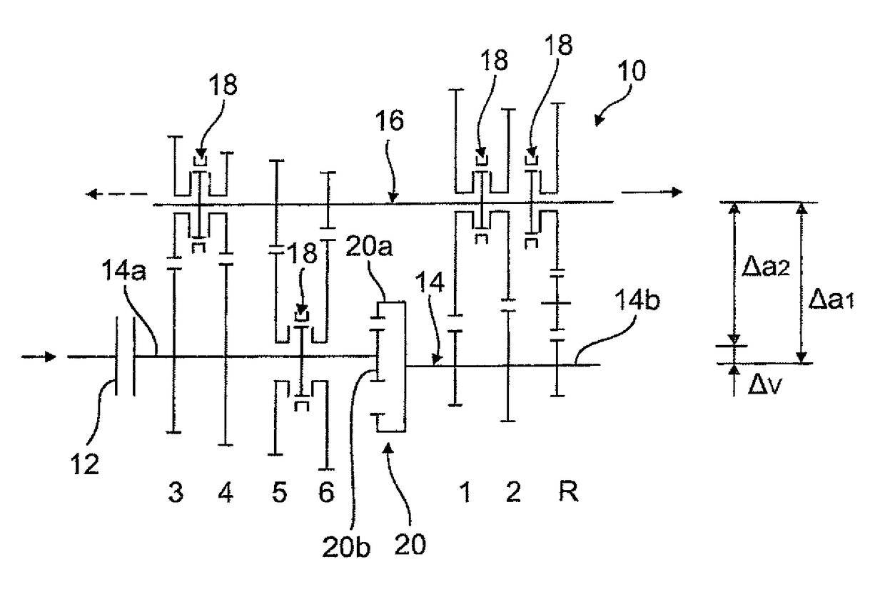
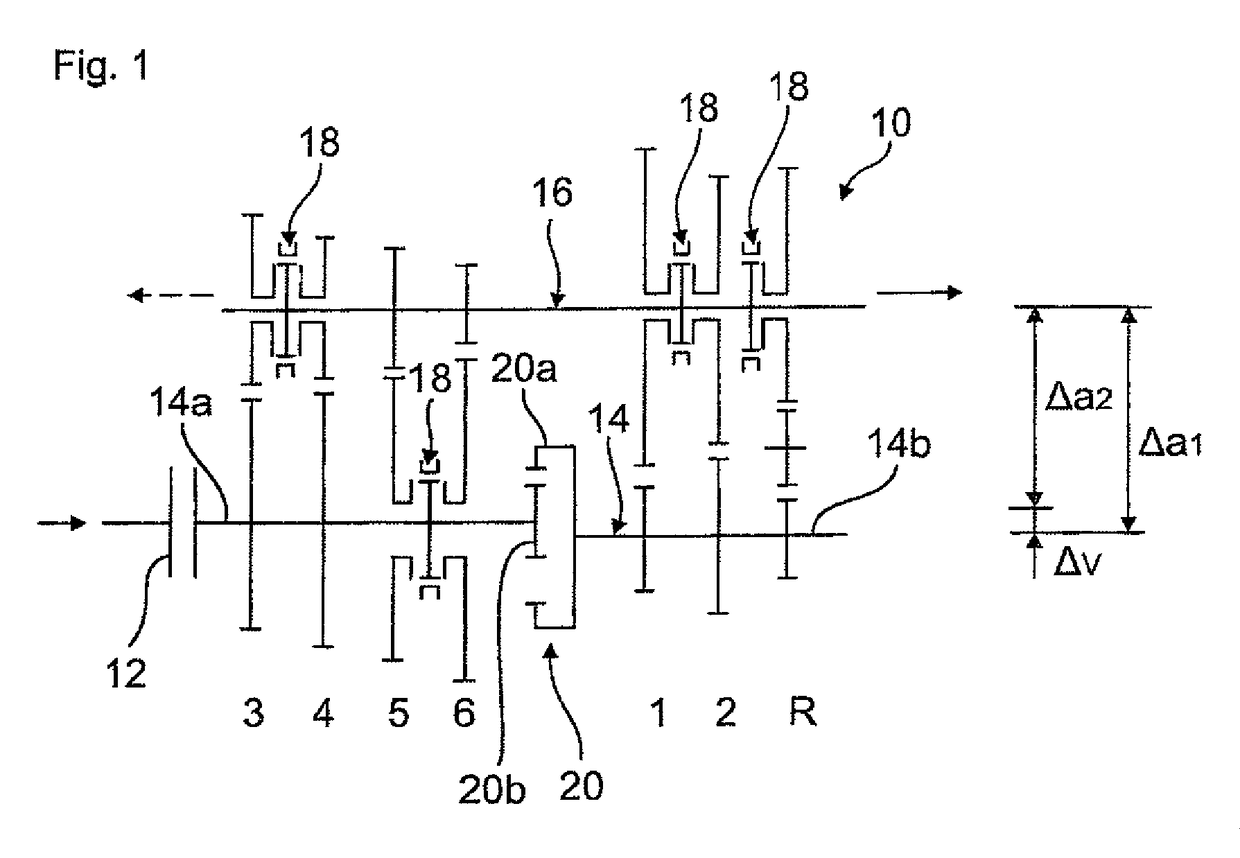
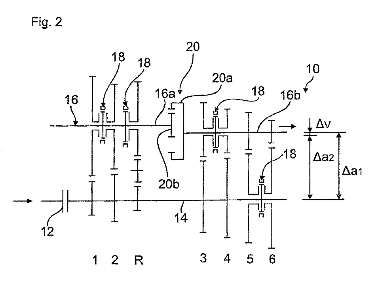
[0024]FIG. 1 shows as block diagram and a change-speed transmission or manual transmission 10 for motor vehicles without transmission housing, with an input shaft 14 which can be connected with a drive aggregate (not shown) via a separating clutch 12, and an output shaft 16.
[0025]Between the shafts 14, 16 meshing gear wheels of gear sets for six forward gears 1 to 6 and a reverse gear R are arranged. The idler gear wheels of the gear sets 1 to 6 and of the reverse gear R are shiftable in a known manner via only schematically indicated synchronous clutches 18 and can thus be connected with the corresponding fixed gear wheel on the respective other shaft 14, 16.
[0026]The two-part input shaft 14 of the transmission 10 is connected via a ring gear stage 20 with a ring gear 20a, which has a greater diameter and internal spline, and with a spur gear wheel 20b, which is in engagement with the ring gear 20a, wherein the subshaft 14a which carries the spur gear wheel 20b, carries the gear wh...
PUM
 Abstract
Description
Claims
Application Information
 - R&D
- Intellectual Property
- Life Sciences
- Materials
- Tech Scout
- Unparalleled Data Quality
- Higher Quality Content
- 60% Fewer Hallucinations
Browse by: Latest US Patents, China's latest patents, Technical Efficacy Thesaurus, Application Domain, Technology Topic, Popular Technical Reports.
© 2025 PatSnap. All rights reserved.Legal|Privacy policy|Modern Slavery Act Transparency Statement|Sitemap|About US| Contact US: help@patsnap.com


