Method, apparatus, and system for encoding and decoding visible light signal

a visible light signal and signal encoding technology, applied in the field of visible light communication, can solve the problems of low transmission rate, data is unlikely to be interfered with or captured, and the amount of information transmitted within a unit time is still low in the conventional method, so as to increase the amount of information transmitted within a unit time and effectively shorten the level duration

Inactive Publication Date: 2017-05-30
KUANG CHI INTELLIGENT PHOTONIC TECH
View PDF12 Cites 0 Cited by
  • Summary
  • Abstract
  • Description
  • Claims
  • Application Information

AI Technical Summary

Benefits of technology

[0005]A technical problem to be solved by the present disclosure is to provide a method, an apparatus, and a system for encoding and decoding a visible light signal to improve an information transmission rate of visible light communication based on an LED.
[0031]In the method, apparatus, and system for encoding and decoding a visible light signal according to the present disclosure, identification data obtained by a mobile phone is divided into several electrical signal units, level durations are used to distinguish between the electrical signal units, and the number of level transitions is used to indicate identification data. In this encoding mode, a receive end can still correctly decode data even if there is a synchronization problem caused by a flashing delay of an LED. In addition, a level duration is adjusted according to a flashing delay, so that the level duration is effectively shortened, thereby increasing an amount of information transmitted within a unit time.

Problems solved by technology

In the wireless light communications technology, data is unlikely to be interfered with or captured, and an optical communication device can be easily made and is unlikely to be damaged or degaussed.
However, during practice, the inventors of the present application found that a transmission rate (namely, an amount of information transmitted within a unit time) in a conventional method is still low.

Method used


Image

  • Method, apparatus, and system for encoding and decoding visible light signal
  • Method, apparatus, and system for encoding and decoding visible light signal
  • Method, apparatus, and system for encoding and decoding visible light signal

Examples


embodiment 1

[0054]An encoding method and a corresponding decoding method in this embodiment are implemented on a mobile phone or a similar portable mobile terminal. The following uses only a mobile phone as an example for description.

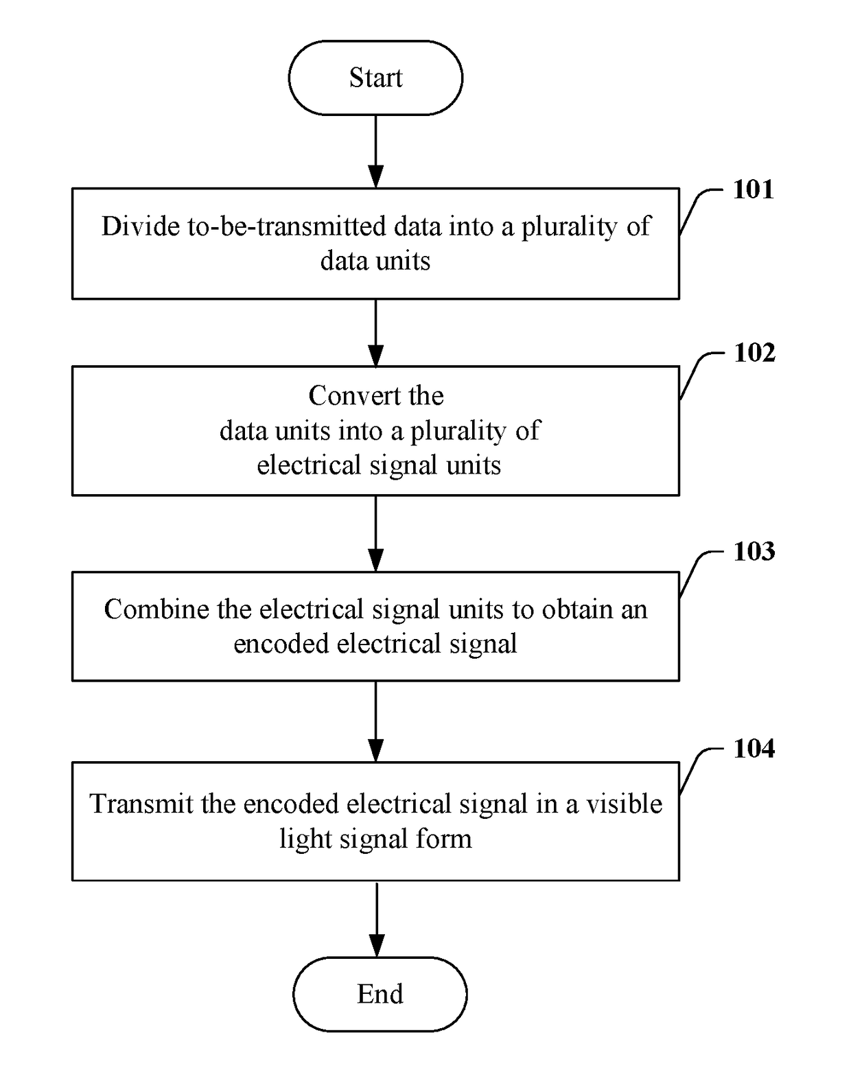
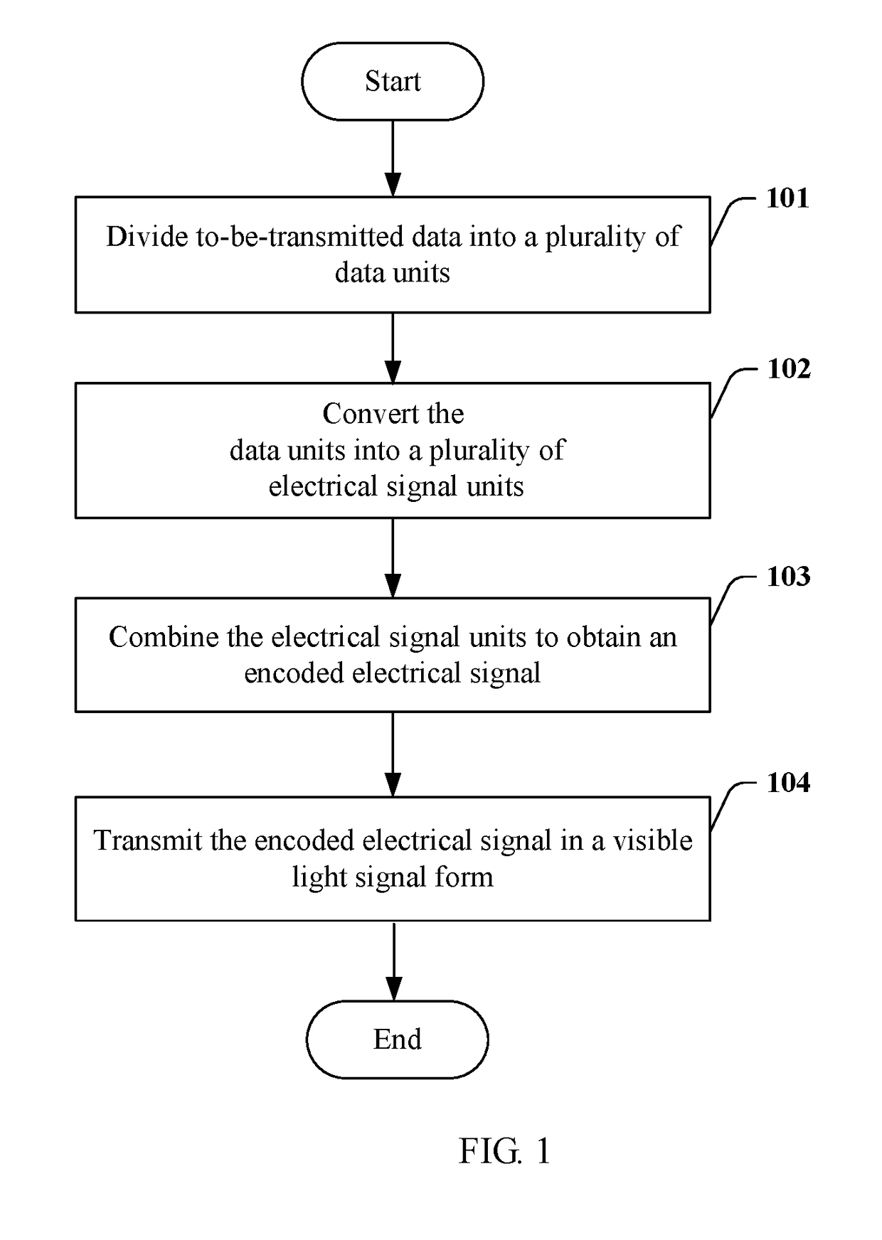
[0055]Referring to FIG. 1, a flowchart of a method for encoding a visible light signal according to Embodiment 1 of the disclosure is provided. The encoding method includes:

[0056]Step 101: Divide to-be-transmitted data into a plurality of data units. Each data unit includes one or more bits. The to-be-transmitted data may be a text, a picture, an audio, and / or a video.

[0057]Step 102: Convert the data units into electrical signal units. For each electrical signal unit, the number of level transitions represents the one or more bits of a corresponding data unit. An interval between adjacent electrical signal units is indicated by a predetermined level. In this embodiment, a rising edge or a falling edge of a level may present a start of a transition.

[0058]For example...

embodiment 2

[0081]In this embodiment, an optical access control system is provided. A mobile phone may be used as a transmit end, and an access control end is used as a receive end. In an alternative embodiment, an optical key is used instead of the mobile phone. The access control end decodes a signal, and may further perform matching by using the signal, and thereby determining whether to open a door.

[0082]FIG. 4 shows a flowchart of a method for encoding a visible light signal according to Embodiment 2 of the disclosure. Referring to FIG. 4, the encoding method is as follows:

[0083]Step 401: Divide to-be-transmitted identification data into a plurality of data units in the mobile phone, where each data unit includes one or more bits.

[0084]Step 402: Convert the data units into electrical signal units. For each electrical signal unit, the number of level transitions is used to represent the one or more bits of a corresponding data unit. An interval indicated by a predetermined level exists betw...

embodiment 3

[0107]This embodiment is implemented in an optical lock system. A dedicated optical key may be used as a transmit end. A controlled end in the optical lock system is used as a receive end. In an alternative embodiment, a mobile phone may be used instead of the optical key. The controlled end in the optical lock system decodes a signal, and may further perform matching by using the signal, thereby determining whether to perform unlocking.

[0108]FIG. 6 shows a flowchart of a method for encoding a visible light signal according to Embodiment 3 of the disclosure. Referring to FIG. 6, the encoding method is as follows:

[0109]Step 601: Divide to-be-transmitted identification data into a plurality of data units. Each data unit includes one or more bits.

[0110]Step 603: Convert the data units into electrical signal units. For each electrical signal unit, the number of level transitions is used to represent the one or more bits of a corresponding data unit. An interval indicated by a predetermi...


PUM


Abstract

The present disclosure provides a method, an apparatus, and a system for encoding and decoding a visible light signal. The encoding method includes the following steps: dividing to-be-transmitted data into a plurality of data units, where each data unit includes one or more bits; converting the data units into a plurality of electrical signal units, where for each electrical signal unit, the number of level transitions is used to represent the one or more bits of a corresponding data unit, and an interval indicated by a predetermined level exists between adjacent electrical signal units, where a level in each electrical signal unit has a first level duration, and the predetermined level between adjacent electrical signal units has a second level duration; combining the electrical signal units to obtain an encoded electrical signal; and transmitting the encoded electrical signal in a visible light signal form.

Description

CROSS REFERENCE TO RELATED APPLICATIONS[0001]This application is a continuation of PCT / CN2014 / 082955 filed on Jul. 24, 2014, which claims priority to Chinese patent application No. 201310328832.1 of Jul. 31, 2013, both of which are incorporated herein by reference.TECHNICAL FIELD OF THE INVENTION[0002]The disclosure relates to visible light communication, and in particular, to a method, an apparatus, and a system for encoding and decoding a visible light signal.BACKGROUND OF THE INVENTION[0003]Visible light communication is an emerging short-range high-speed wireless light communications technology that is developed on a basis of an LED technology. A basic principle of visible light communication is that communication is performed by flashing an LED light source at a high frequency based on a characteristic that a switching speed of a light emitting diode (LED) is higher than that of a fluorescent lamp and an incandescent lamp. Presence of light represents binary 1, and absence of l...

Claims


Application Information

Patent Timeline
Patent Type & Authority Patents(United States)
IPC IPC(8): H04B10/116
CPCH04B10/116
Inventor LIU, RUOPENGFAN, LINYONG
Owner KUANG CHI INTELLIGENT PHOTONIC TECH
Why Eureka
Try Eureka