Electrooptical modulator

An electro-optic modulator and modulation electrode technology, which is applied in the directions of instruments, optics, nonlinear optics, etc., can solve the problems of low modulation efficiency and low information transmission rate of electro-optic modulators, and achieve the effect of improving modulation efficiency and information transmission rate

Inactive Publication Date: 2014-11-12
HONG FU JIN PRECISION IND (SHENZHEN) CO LTD +1
View PDF5 Cites 0 Cited by
  • Summary
  • Abstract
  • Description
  • Claims
  • Application Information

AI Technical Summary

Problems solved by technology

Current electro-optic modulators generally transmit and modulate light waves including transverse electric waves and transverse magnetic waves, or only transmit and modulate transverse electric waves, or only transmit and modulate transverse magnetic waves. Modulation, its modulation efficiency is low, resulting in a low information transmission rate of the electro-optic modulator

Method used


Image

  • Electrooptical modulator
  • Electrooptical modulator

Examples


Embodiment Construction

[0011] The embodiments of the present invention will be further described in detail below in conjunction with the accompanying drawings.

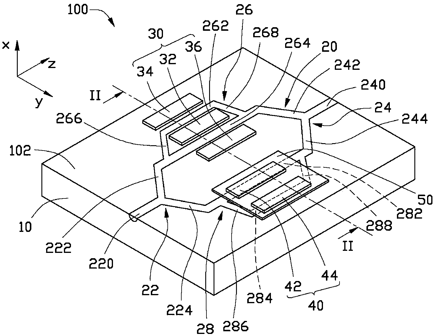
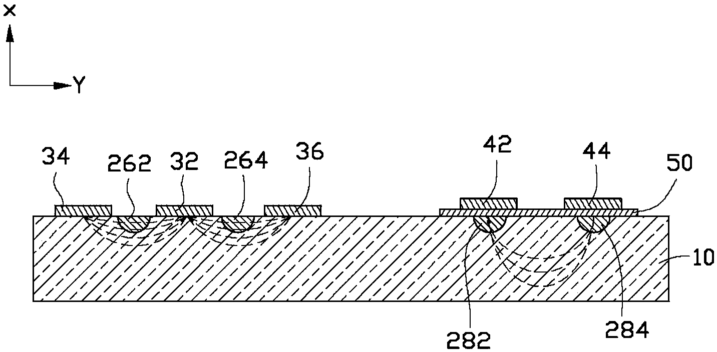
[0012] see figure 1 , The electro-optic modulator 100 provided by the embodiment of the present invention includes a substrate 10 , an optical waveguide 20 , a first modulation electrode assembly 30 and a second modulation electrode assembly 40 .

[0013] The substrate 10 includes a top surface 102 . Since lithium niobate crystal has a relatively high reaction speed, in this embodiment, the material of the substrate 10 is lithium niobate crystal, so as to increase the bandwidth of the electro-optic modulator 100 .

[0014] The optical waveguide 20 is formed by diffusing from the top surface 102 to the interior of the substrate 10 . The optical waveguide 20 includes a Y-shaped incident portion 22 , a Y-shaped outgoing portion 24 , a first connecting portion 26 and a second connecting portion 28 .

[0015] The Y-shaped incident portion 22 ...


PUM


Abstract

The invention relates to an electrooptical modulator comprising a substrate, an optical waveguide, a first modulation electrode component and a second modulation electrode component. The optical waveguide comprises a Y-shaped incidence part, a Y-shaped emitting part, a first connecting part and a second connecting part, wherein the first connecting part is used for transmitting transverse electric waves only and the second connecting part is used for transmitting transverse magnetic waves only. The first connecting part is connected with the Y-shaped incidence part and the Y-shaped emitting part and comprises a first branch and a second branch. The second connecting part is connected with the Y-shaped incidence part and the Y-shaped emitting part and comprises a third branch and a fourth branch. The first modulation electrode component comprises a first ground electrode, a first modulation electrode and a second modulation electrode, wherein the first ground electrode is arranged between the first branch and the second branch, the first modulation electrode is arranged on one side, away from the first ground electrode, of the first branch, and the second modulation electrode is arranged on one side, away from the first ground electrode, of the second branch. The second modulation electrode component comprises a second ground electrode and a third modulation electrode which cover the third branch and the fourth branch respectively.

Description

technical field [0001] The invention relates to a high-speed optical communication system, in particular to an electro-optic modulator. Background technique [0002] An existing electro-optic modulator uses the electro-optic effect to change the refractive index of one of the two branches of the optical waveguide by modulating the electric field, thereby changing the phase of the light wave transmitted in it, so that it is different from the light wave transmitted in the other branch of the optical waveguide. There is a phase difference. In this way, the light waves transmitted in the two branches of the optical waveguide will interfere after reconverging, and the output light energy depends on the phase difference, that is, it is determined by the modulation electric field, thereby realizing modulation. However, with the rapid development of information technology, the information transmission rate (bandwidth) has become the main consideration of technology development. C...

Claims


Application Information

Patent Timeline
Patent Type & Authority Applications(China)
IPC IPC(8): G02F1/035
Inventor 黄新舜
Owner HONG FU JIN PRECISION IND (SHENZHEN) CO LTD
Why Eureka
Try Eureka