Powered working machine

a working machine and power technology, applied in the direction of power-driven reciprocating saws, manufacturing tools, portable power-driven tools, etc., can solve problems such as complicated work, and achieve the effect of facilitating attachment/detachmen

Active Publication Date: 2017-06-06
KOKI HLDG CO LTD
View PDF16 Cites 11 Cited by
  • Summary
  • Abstract
  • Description
  • Claims
  • Application Information

AI Technical Summary

Benefits of technology

[0006]An object of the present invention is to provide a powered working machine that facilitates a work of attachment / detachment of a tip tool to / from a tool supporting unit.
[0009]According to the present invention, the tip tool can be attached / detached to / from the tool supporting member without rotating the tool fixing member, so that the work can be facilitated.

Problems solved by technology

However, in the powered working machine described in Patent Document 1, when the operator perform a work of attachment / detachment of the tip tool to / from the tool supporting unit, the operator has to rotate the bolt, and therefore, the work is complicated.

Method used


Image

  • Powered working machine
  • Powered working machine
  • Powered working machine

Examples


configuration example 1

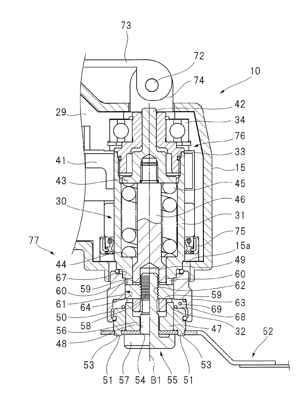
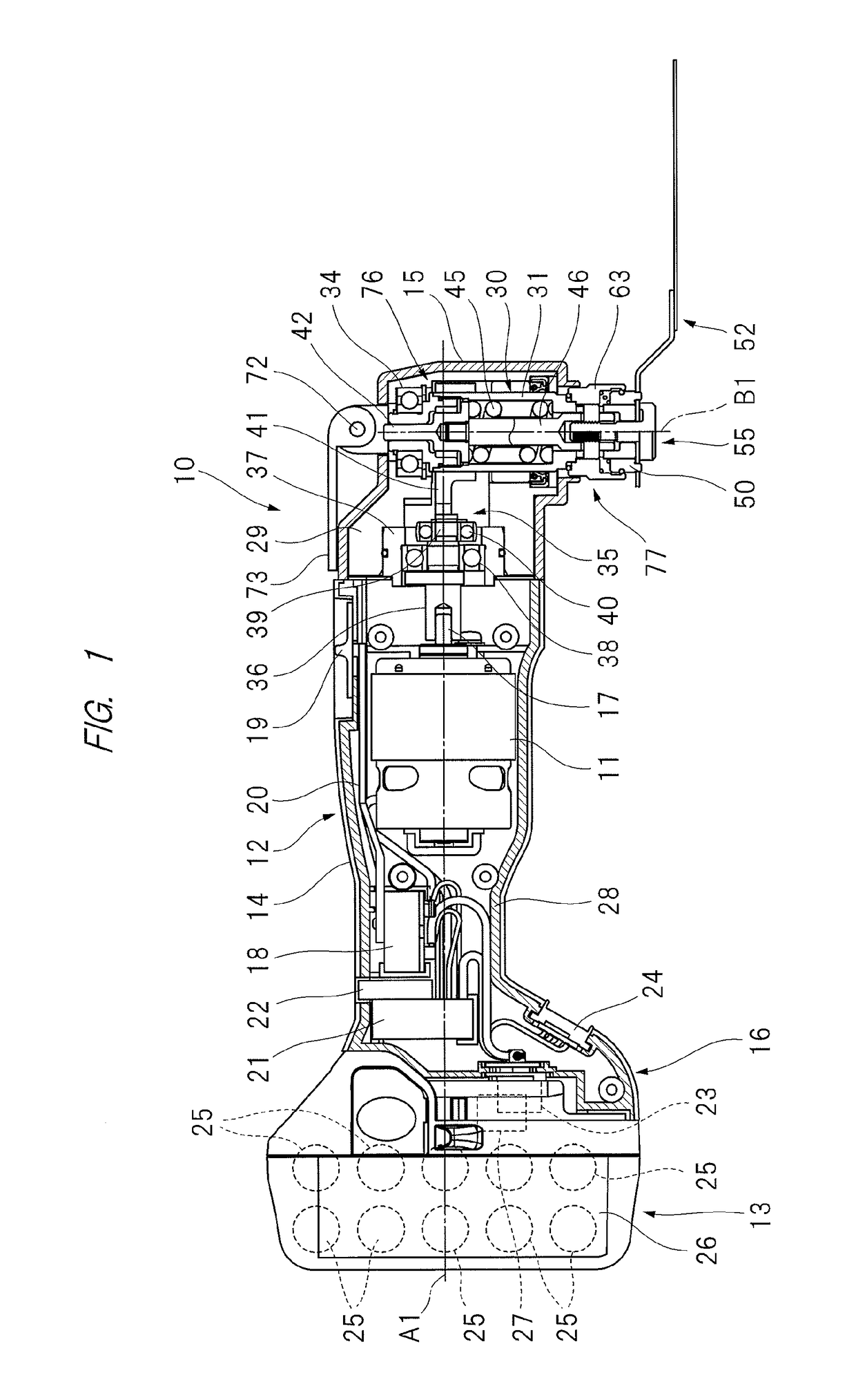
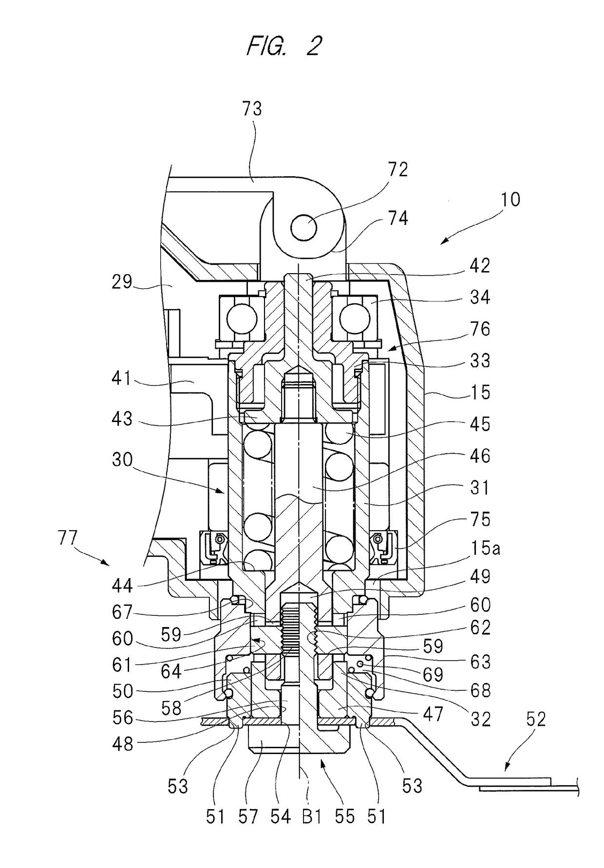
[0092]A powered working machine which drives a tip tool with power of a driving source, includes: a tool supporting member to which the tip tool is fixed; a tool fixing member which can be attached / detached to / from the tool supporting member, which is attached to the tool supporting member, and which cooperates with the tool supporting member to clamp and fix the tip tool from both sides of the tool supporting member in a direction along an axis line; a lock member which is movable in a direction crossing the axis line and which engages with the tool fixing member; and a switching member which is arranged outside the lock member in the crossing direction, which can rotate so as to center the axis line, and which can be switched between a first rotation position at which the lock member cannot move in the crossing direction and a second rotation position at which the lock member can move in the crossing direction.

configuration example 2

[0093]In the powered working machine described in the configuration example 1, a rotation preventing mechanism that holds the switching member at the first rotation position is provided.

configuration example 3

[0094]In the powered working machine described in the configuration example 2, the switching member has a guide hole in which the lock member is arranged, and, as a diameter of the guide hole, an inner diameter of a portion where the switching member is at the second rotation position so that the lock member can move in the crossing direction is larger than an inner diameter of a portion where the switching member is at the first rotation position so that the lock member cannot move in the crossing direction.


PUM

PropertyMeasurementUnit
forceaaaaaaaaaa
inner diameteraaaaaaaaaa
circumferenceaaaaaaaaaa

Abstract

A powered working machine facilitating work of fixing a tip tool to a tool supporting member is provided. A powered working machine in which a tip tool is driven by power of an electric-powered motor includes: an output shaft to which the tip tool is attached; a tool fixing member which fixes the tip tool to the output shaft; a second shaft to / from which the tool fixing member is attached / detached; a clamp having a locked state in which a state of attachment of the tool fixing member to the second shaft is maintained and an unlocked state in which the tool fixing member can be detached from the second shaft; and a guide member having a first rotation position at which the clamp is in the locked state and a second rotation position at which the clamp is in the unlocked state.

Description

CROSS-REFERENCE TO RELATED APPLICATION[0001]The present application claims priority from Japanese Patent Application No. 2013-273075 filed on Dec. 27, 2013, the content of which is hereby incorporated by reference into this application.TECHNICAL FIELD OF THE INVENTION[0002]The present invention relates to a powered working machine having a tip tool driven by power from an electric-powered working motor serving as a driving source.BACKGROUND OF THE INVENTION[0003]An electric-powered working machine that actuates a tip tool by power from an electric-powered motor serving as a driving source so as to perform hand working has been conventionally known, and such an electric-powered working machine is described in Japanese Patent Application Laid-Open Publication No. 2012-232381 (Patent Document 1). The powered working machine described in Patent Document 1 includes: a machine main body; an electric-powered motor housed in the machine main body; a power converting mechanism arranged insid...

Claims


Application Information

Patent Timeline
Patent Type & Authority Patents(United States)
IPC IPC(8): B25F5/02B23D51/10B27B19/00B24B45/00B27B5/32B24B23/04B24B27/08B23B31/10
CPCB25F5/02B23D51/10B24B23/04B24B27/08B24B45/006B27B5/32B27B19/006B23B31/10Y10T279/33
Inventor ITO, YUTAKAOGAWA, ITSUSHITOUKAIRIN, JUNICHIENTA, JYUN
Owner KOKI HLDG CO LTD
Why Eureka
Try Eureka