
Isolators including damper assemblies having variable annuli and spacecraft isolation systems employing the same

a technology of annulus and damper assembly, which is applied in the field of isolation systems, can solve the problems of increasing the cost of spacecraft isolation systems, increasing labor costs and extended manufacturing schedules, and reducing the efficiency of launch locks, so as to reduce the transmission of vibrations

Inactive Publication Date: 2017-06-06
HONEYWELL INT INC
View PDF12 Cites 3 Cited by
  • Summary
  • Abstract
  • Description
  • Claims
  • Application Information

AI Technical Summary

Benefits of technology

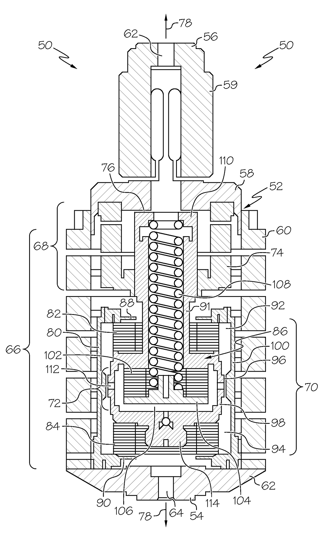
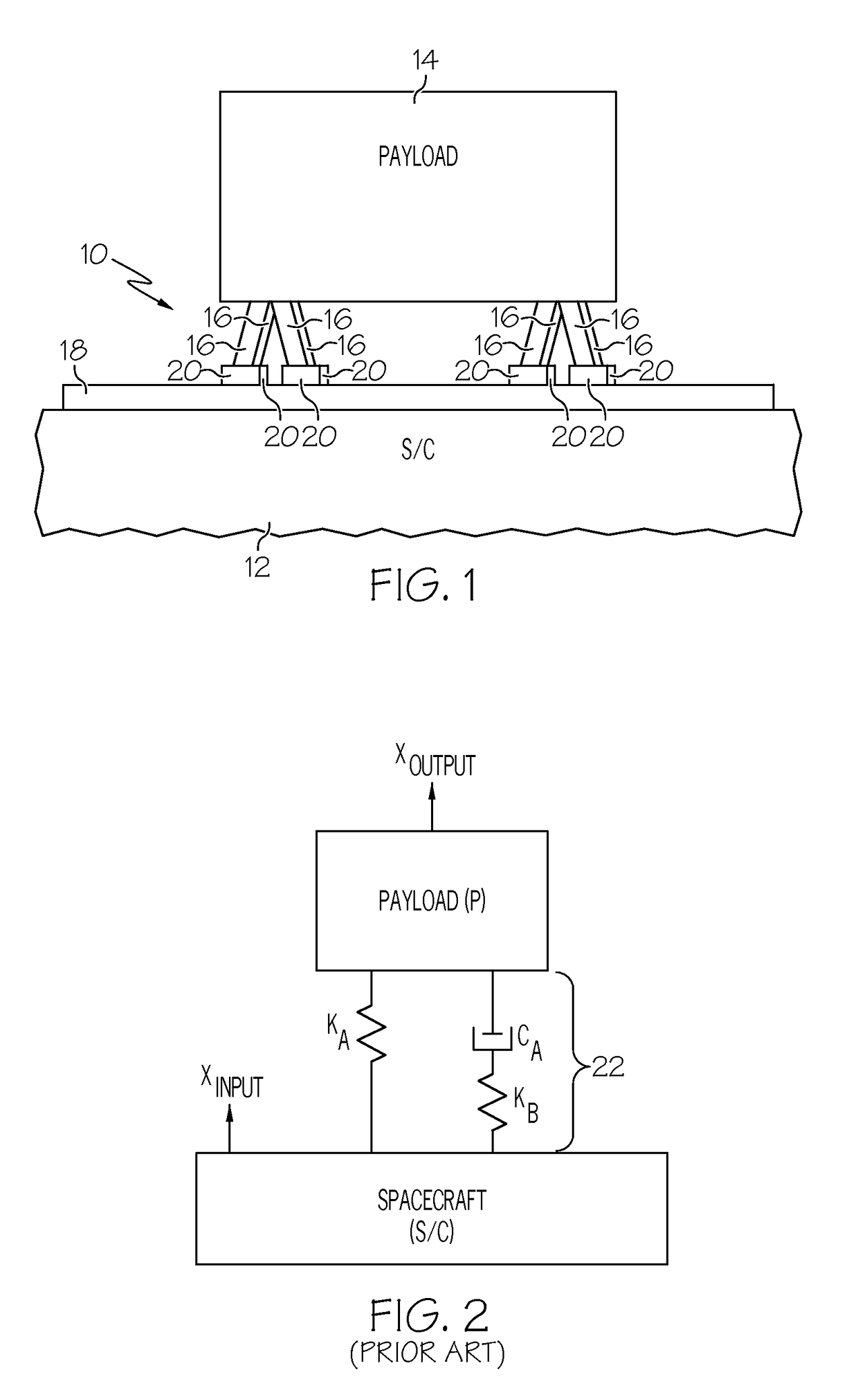
The patent describes a system for reducing vibrations in a spacecraft and its payload. It includes three parameter isolators that have a main spring, a secondary spring, and a damper assembly with a damping fluid and a movable piston. The system also has a variable annulus fluid that changes its flow area as the piston moves. The technical effect of this invention is to minimize vibration transfer between the spacecraft and its payload, leading to improved stability and efficiency.

Problems solved by technology

However, while generally effective at protecting the isolation from high impact loads during launch, the usage of launch locks is associated with a number of disadvantages.
The usage of multiple launch locks adds additional part count, weight, and hardware cost to the spacecraft isolation system.
Initial set-up and fine tuning of launch locks can be labor intensive resulting in higher labor costs and extended manufacturing schedules.
As a still further drawback, launch locks are typically actuated utilizing pyrotechnic devices, which can be unreliable and which tend to produce undesirably high shock forces when detonated potentially disrupting the payload or spacecraft components.
Finally, as launch locks shunt vibrational forces around the isolators directly between the spacecraft and payload, the usage of launch lock systems results in limited isolation of the payload during spacecraft launch.

Method used


Image

  • Isolators including damper assemblies having variable annuli and spacecraft isolation systems employing the same
  • Isolators including damper assemblies having variable annuli and spacecraft isolation systems employing the same
  • Isolators including damper assemblies having variable annuli and spacecraft isolation systems employing the same

Examples


Embodiment Construction

[0016]The following Detailed Description is merely exemplary in nature and is not intended to limit the invention or the application and uses of the invention. Furthermore, there is no intention to be bound by any theory presented in the preceding Background or the following Detailed Description. While primarily described below in the context of a single degree-of-freedom (axially-damping), three parameter isolator deployed within a multi-point spacecraft isolation system, it is emphasized that embodiments the damper assembly including a variable annulus can be integrated into other types of isolators, such as three parameter isolators providing isolation in multiple degrees-of-freedom and two parameter isolators. Furthermore, embodiments of the below-described isolator can be employed in multi-point isolation systems other than spacecraft isolation systems, such as terrestrial, waterborne, and airborne isolation systems.

[0017]Three parameter isolators commonly include a damper asse...


PUM


Abstract

Embodiments of an isolator are provided, as are embodiments of a spacecraft isolation system employing a number of three parameter isolators. In one embodiment, the isolator includes a damper assembly and a thermal compensator external to the damper assembly. The damper assembly includes, in turn, a damper housing and a first hydraulic chamber, which is located within the damper housing and which is configured to contain a damping fluid. The thermal compensator includes a thermal compensator chamber, which is fluidly coupled to the first hydraulic chamber and which is configured to exchange damping fluid therewith during operation of the isolator. A thermal compensator bellows bounds an inner circumference of the thermal compensator chamber such that the bellows is externally pressurized when the first hydraulic chamber and the thermal compensator chamber are filled with the damping fluid.

Description

TECHNICAL FIELD[0001]The present invention relates generally to spacecraft isolation systems and, more particularly, to embodiments of an isolator, such as a three parameter isolator, having a damper assembly in which the flow area across an annulus varies as a function of piston stroke.BACKGROUND[0002]Control moment gyroscope arrays, reaction wheel arrays, and other such devices deployed onboard a satellite or other spacecraft for attitude adjustment purposes generate vibratory forces during operation. Vibration isolation systems are commonly employed to minimize the transmission of vibratory forces emitted from such attitude adjustment devices, through the spacecraft body, to any vibration-sensitive components (e.g., optical payloads) carried by the spacecraft. Vibration isolation systems commonly include a number of individual vibration isolators (typically three to eight isolators), which are positioned between the spacecraft payload and the spacecraft body in a multi-point moun...

Claims


Application Information

Patent Timeline
Patent Type & Authority Patents(United States)
IPC IPC(8): F16F15/02F16F9/48F16F9/32B64G1/22F16F13/00
CPCF16F15/022B64G1/22F16F9/3235F16F9/483B64G2001/228F16F13/007B64G1/228
Inventor MARTINEZ, DANIELPAGAN, JOSEGOOLD, RYAN
Owner HONEYWELL INT INC
Learn More