Voltage detecting device

a technology of voltage detection and detection circuit, which is applied in the direction of transporting and packaging, indicating/monitoring circuit, and arranging for several simultaneous batteries, etc., and can solve problems such as errors in daisy chain communication

Active Publication Date: 2017-06-06
HITACHI ASTEMO LTD
View PDF9 Cites 1 Cited by
  • Summary
  • Abstract
  • Description
  • Claims
  • Application Information

AI Technical Summary

Benefits of technology

[0005]The present invention reduces susceptibility to noise, and thus improves daisy chain communication performance.
[0007]According to this embodiment, it is possible to reduce susceptibility to noise, and perform daisy chain communication ideally.

Problems solved by technology

In JP '074, due to the effect of path impedance of a bus bar, a wire harness, and the like between cell controllers adjacent to each other, a voltage difference occurs between the cell controllers, noise enters depending on a frequency band, and consequently an error may occur in daisy chain communication (corresponding to the above-described serial communication) by the cell controllers.

Method used


Image

  • Voltage detecting device
  • Voltage detecting device
  • Voltage detecting device

Examples


Embodiment Construction

[0016]One embodiment of the invention is described with reference to the drawings.

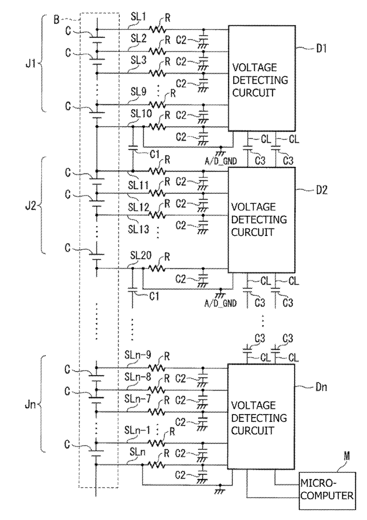
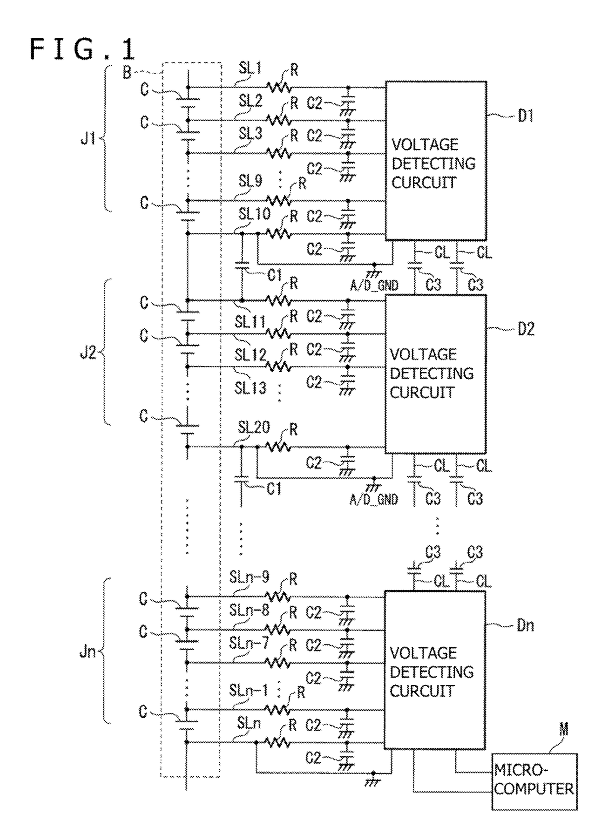
[0017]A voltage detecting device according to the invention is mounted in a moving vehicle such as an EV (Electric Vehicle), a HV (Hybrid Vehicle), or the like, and monitors voltage states of battery cells C of battery modules J1 to Jn constituting a battery B. As shown in FIG. 1, the voltage detecting device includes voltage detecting lines SL1 to SLn, first capacitors C1, resistors R, second capacitors C2, third capacitors C3, voltage detecting circuits D1 to Dn, and a microcomputer M. The first capacitors C1, the second capacitors C2, the resistors R, the third capacitors C3, the voltage detecting circuits D1 to Dn, and the microcomputer M are mounted on a board not shown in the figures.

[0018]The voltage detecting lines SL1 to SLn are conductors that connect the battery cells C to the voltage detecting circuits D1 to Dn. The voltage detecting circuits D1 to Dn detect the voltages of powers of the re...


PUM


Abstract

A voltage detecting device includes a plurality of voltage detecting circuits provided for battery modules of a battery, the battery being formed by connecting, in series with each other, the battery modules each formed by connecting battery cells in series with each other, the plurality of voltage detecting circuits being configured to detect voltage of each of the battery cells; a plurality of voltage detecting lines connecting the battery cells to the voltage detecting circuits; and a control device controlling charge and discharge of the battery cells on a basis of detection information obtained from the voltage detecting circuits, a voltage detecting line having a lowest potential being connected to one of the voltage detecting circuits and a voltage detecting line having a highest potential being connected to the other of the voltage detecting circuits, being adjacent and connected to each other via a first capacitor.

Description

CROSS REFERENCE TO RELATED APPLICATION[0001]The present application claims priority under 35 U.S.C. §119 to Japanese Patent Application No. 2014-007218 filed in the Japan Patent Office on Jan. 17, 2014, the entire content of which is hereby incorporated by reference.TECHNICAL FIELD[0002]The present invention relates to a voltage detecting device.BACKGROUND OF THE INVENTION[0003]A storage battery managing control device that can improve the reliability of serial communication is disclosed in Japanese patent laid-open publication No. 2008-220074 (“JP '074”), which describes the storage battery managing control device having a configuration formed by connecting a plurality of cell controllers and a battery controller to each other in a chained manner for serial communication. In this storage battery managing control device, the battery controller or the cell controllers includes a communication speed detecting means for detecting the communication speed of data input from another contr...

Claims


Application Information

Patent Timeline
Patent Type & Authority Patents(United States)
IPC IPC(8): H02J7/00
CPCH02J7/0021H02J7/0014Y02T10/7055Y02T10/70H02J7/0013H02J7/0047
Inventor MIYAJIMA, KAZUYA
Owner HITACHI ASTEMO LTD
Why Eureka
Try Eureka