
Adaptive over-current detection

a technology of over-current detection and over-current, applied in the direction of emergency protective arrangements for limiting excess voltage/current, power conversion systems, electrical appliances, etc., can solve the problems of difficult and reliable detection of the presence of over-current (oc), on which circuit protection relies, and many problems in the detection of over-current, so as to improve the accuracy of over-current detection and reduce the chip area , the effect of low susceptibility to nois

Active Publication Date: 2005-10-04
TEXAS INSTR INC
View PDF4 Cites 1 Cited by
  • Summary
  • Abstract
  • Description
  • Claims
  • Application Information

AI Technical Summary

Benefits of technology

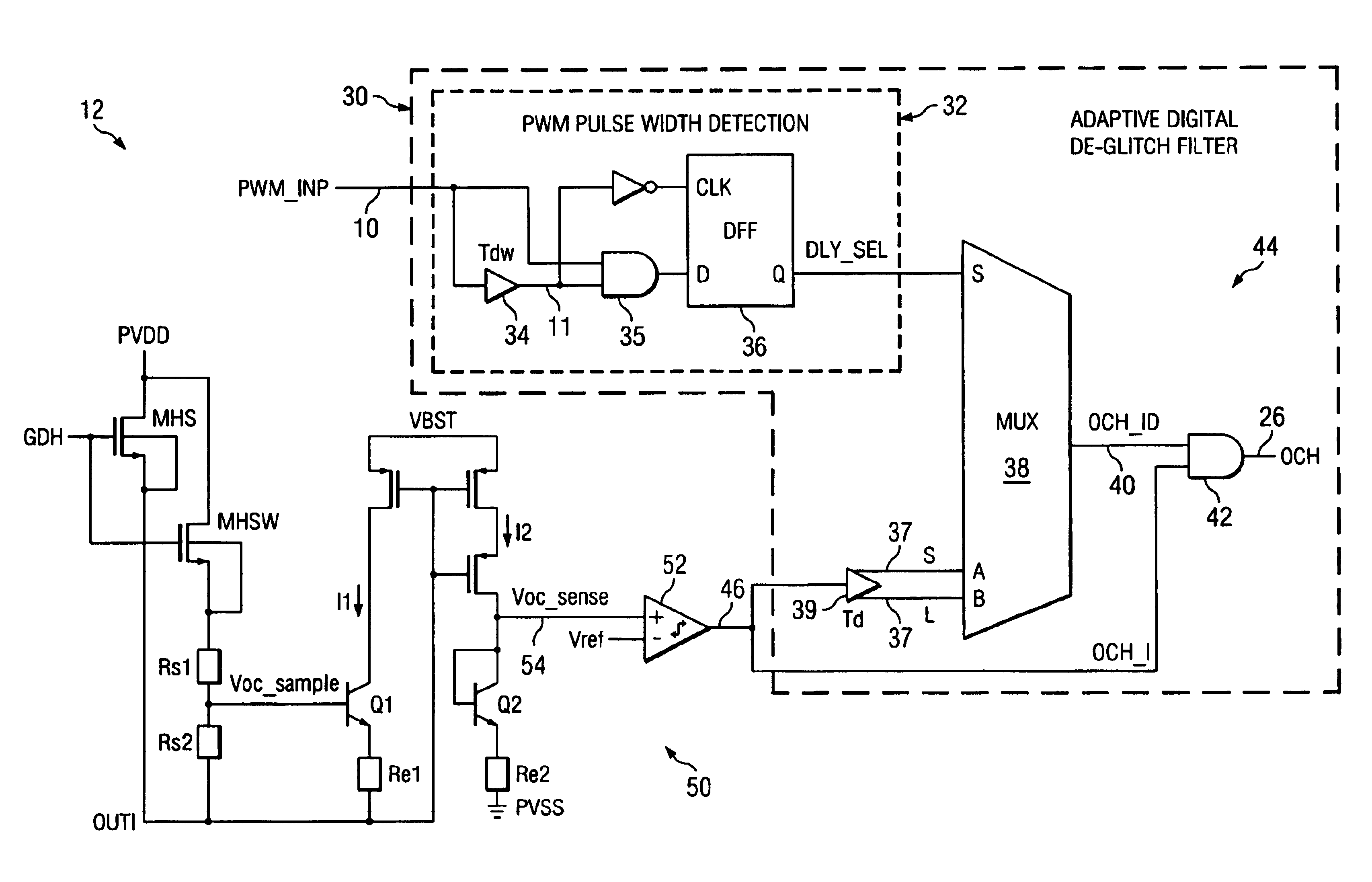
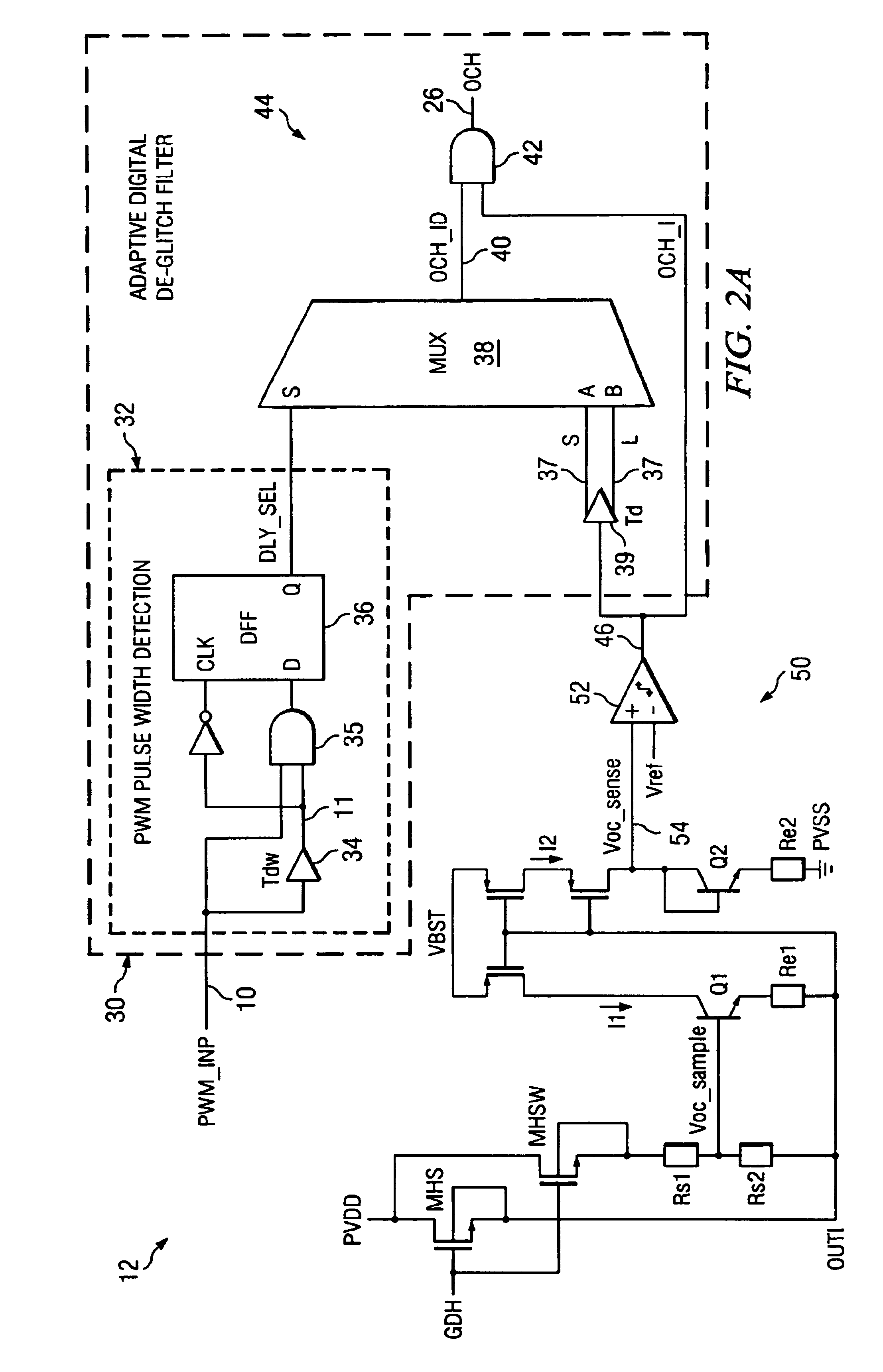
The present invention provides methods and circuits for over-current detection in PWM circuits using digital processing techniques. The methods and circuits have advantages over prior art, including improved accuracy, low susceptibility to noise, reduced chip area, and decreased cost. The invention includes detecting the pulse width of the PWM signal and selecting a digital delay less than the pulse width. An over-current condition in the PWM power stage circuit is detected, and the over-current detection signal is filtered out by means of logically AND'ing with the delayed OC detection signal. The output of the AND gate is the final over-current detection signal. The invention also provides a plurality of selectable digital delays for selection in accordance with the detected PWM pulse width. The duration of the selectable digital delays is less than one half of a pre-selected minimum pulse width expected for the PWM circuit. The invention also includes a circuit for over-current detection that has a plurality of selectable digital delay paths and a pulse width detection circuit. The invention uses digital logic means to indicate the detection of an over-current detection signal having the duration equal to or greater than the PWM pulse width.

Problems solved by technology

In practice, the reliable detection of the presence of over-current (OC) upon which circuit protection relies can be difficult due to some limitations.
In power output stage circuitry, and gate drive circuitry in particular, the detection of over-current is complicated by the presence of noise, mainly due to ground bouncing and reverse recovery of power devices (either BJT or MOSFET).
Analog filtering solutions are beset with many problems, however, including variability due to power supply and process variations and imperfectly matched over-current detection circuit components.
As a result of these shortcomings, the over-current detection circuits known in the arts are subject to a tendency to erroneously report the existence of an over-current condition when such a condition does not in fact exist, causing unwanted interruptions and delays.
Failure to detect over-current conditions as they occur, however, may permit excessive current to damage the device.

Method used


Image

  • Adaptive over-current detection
  • Adaptive over-current detection
  • Adaptive over-current detection

Examples


Embodiment Construction

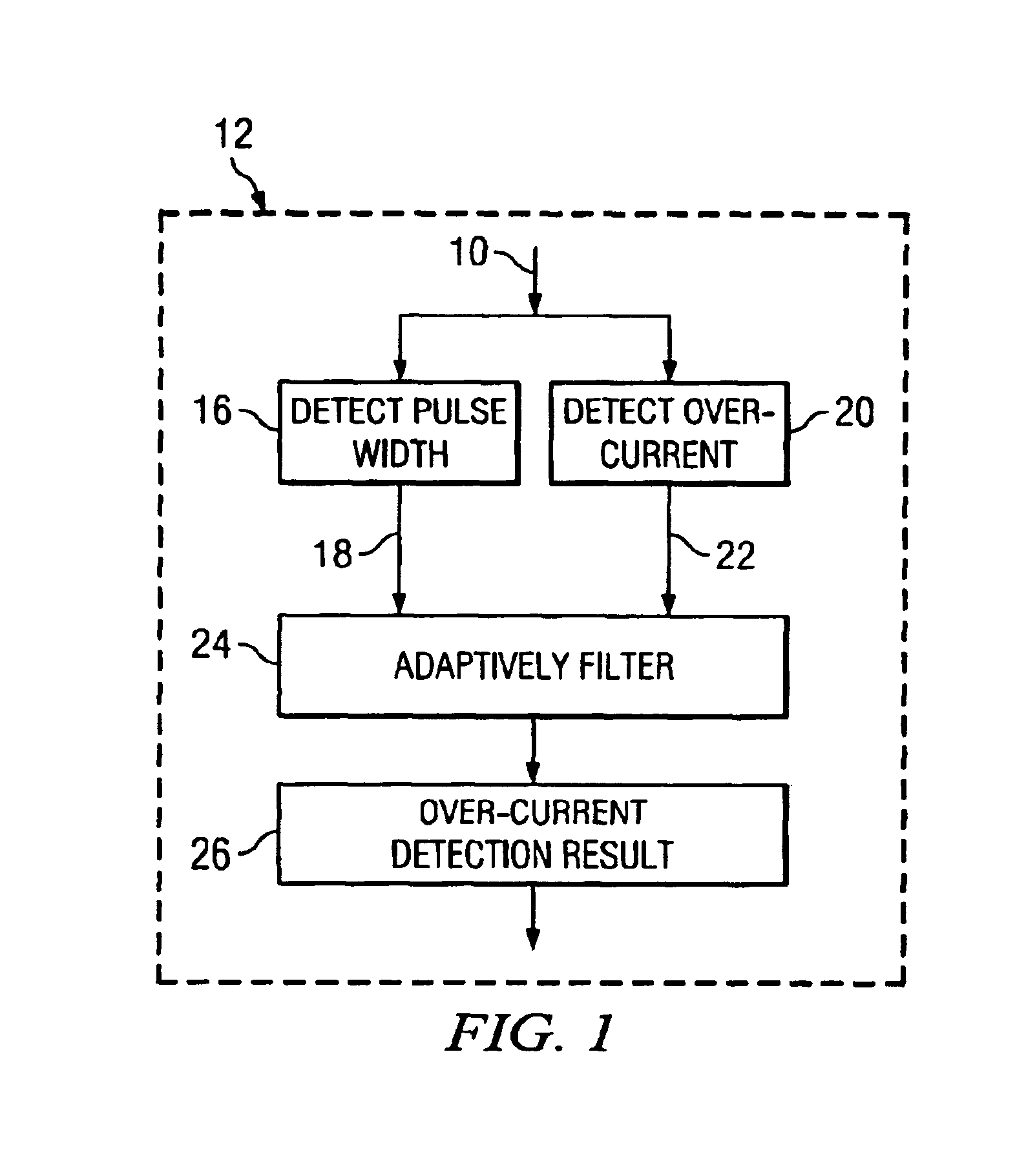
[0021]In general, the preferred embodiments of the invention provide over-current protection solutions particularly useful for PWM power stages. Referring first primarily to the process flow diagram of FIG. 1, a PWM signal 10 in a PWM switching circuitry 12 is monitored. The pulse width of the PWM signal 10 is detected, as shown at step 16. As indicated by arrow path 18, the pulse width is subsequently used to adaptively filter 24 out the noises in any detected over-current condition. Over-current conditions are detected as shown at step 20. An indication of a detected over-current condition, shown by arrow path 22, is provided. At step 24, the over-current indication 22 is adaptively filtered. It should be noted that the adaptive filtering is performed in step 24 by eliminating false over-current indications in 22. This is preferably accomplished by means of eliminating over-current indications 22 for events shorter than a propagation delay selected based upon the determination of ...


PUM


Abstract

Disclosed are methods and apparatus for over-current detection in PWM power stages. Disclosed methods and apparatus provide over-current detection with adaptive filtering according to the pulse width of the PWM input signal. Methods and apparatus for their implementation are described for detecting the pulse width of a PWM signal in the PWM circuit. According to the detected pulse width, a digital delay less than the pulse width of the PWM signal is selected from among a plurality of available digital delays. Further, an over-current condition in the PWM power stage is detected. The detected over-current signal is filtered by means of the selected digital delay and an over-current detection result is output.

Description

TECHNICAL FIELD[0001]The invention relates to over-current detection in electronic circuits. More particularly, the invention relates to methods and circuits for over-current detection in pulse width modulation (PWM) power stage integrated circuits (ICs) and gate drive ICs. PWM power stage ICs and gate drive ICs are used in switching power supply applications, DVD players, A / V receivers, home theater, and other audio applications.BACKGROUND OF THE INVENTION[0002]Protecting electronic circuits from malfunctioning or becoming damaged by exposure to excessive current has long been a critical requirement. In practice, the reliable detection of the presence of over-current (OC) upon which circuit protection relies can be difficult due to some limitations. In power output stage circuitry, and gate drive circuitry in particular, the detection of over-current is complicated by the presence of noise, mainly due to ground bouncing and reverse recovery of power devices (either BJT or MOSFET). ...

Claims


Application Information

Patent Timeline
Patent Type & Authority Patents(United States)
IPC IPC(8): H02H7/10H02M1/12H02M1/08
CPCH02M1/08H02M1/32
Inventor JIANG, JIANDONG
Owner TEXAS INSTR INC
Learn More