
Gas-based microfluidic devices and operating methods thereof

a microfluidic device and gas-based technology, applied in the field of gas-based microfluidic devices and operating methods thereof, can solve the problems of high cost of training technicians and purchasing instruments, lack of ability to own an in-house laboratory, and inability to prepare samples and solve problems such as unprocessed solutions spilling, etc., to suppress the spilling of unprocessed solutions, easy to manufacture and use, and stable results

Active Publication Date: 2017-06-13
ZHEJIANG PUSHKANG BIOTECHNOLOGY CO LTD
View PDF2 Cites 0 Cited by
  • Summary
  • Abstract
  • Description
  • Claims
  • Application Information

AI Technical Summary

Benefits of technology

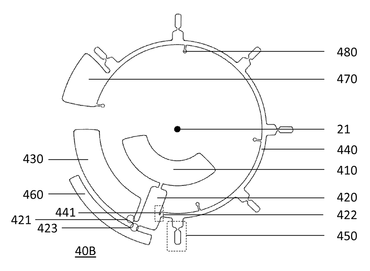
[0011]At least one embodiment of the present invention provides a gas-based microfluidic device. The microfluidic device is easy to manufacture and use, but provides stable results. The gas-based microfluidic device comprises a drive module and a microfluidic platform. The drive module is configured to rotate the microfluidic platform when the microfluidic platform is mounted on the drive module. The microfluidic platform comprises a center of rotation and at least one microfluidic element, where each of the at least one microfluidic element comprises an injection chamber, a process chamber, an air chamber, an overflow channel, at least one detection chamber, and a barrier. More particularly, the injection chamber is disposed at a place near the center of rotation and configured to accept a solution. Relative to the injection chamber, the process chamber is disposed at a peripheral place on the microfluidic platform and is connected to the injection chamber. The process chamber is also connected to the air chamber and the overflow channel respectively, and connected with the at least one detection chamber through the overflow channel. The barrier is configured between the process chamber and the overflow channel to suppress the spilling of unprocessed solutions.
[0013]At least one embodiment of the present invention shows a better efficiency on sample preparation. The drive module in a gas-based microfluidic device may be used to purify samples for reactions. The gas-based microfluidic device separates substances with different densities, based in part on the density gradient, in a short time and thus largely improves test results.
[0015]At least one embodiment of the present invention provides stable and reproducible results. The gas-based microfluidic device, for example, can be used to transfer processed solutions to the at least one detection chamber simultaneously by the gases in the air chamber. The transference based on gases can reduce man-made errors and diminish variations among detection chambers. The gas-based microfluidic device therefore shows a better performance on stability and reproducibility.
[0016]At least one embodiment of the present invention provides a fast and easy method to operate microfluidic devices. In some embodiments, the gas-based microfluidic devices finish the sample preparation and sample dispensation in one acceleration / deceleration cycle. In the acceleration stage, the gas-based microfluidic device increases the rotational speed and utilizes the centrifugal force for sample preparation; in the deceleration stage, the gas-based microfluidic device decreases the rotational speed and utilizes the decompressing gases to transfer the processed samples to the at least one detection chamber evenly.

Problems solved by technology

Sample preparation and solution metering are complex tasks in the art of analysis, in which both require well-trained technicians and advanced instruments to perform.
However, costs on training technicians and purchasing instruments built a high barrier to found an analysis laboratory.
Large institutes such as research centers and hospitals may be capable of affording an analysis department, but local workshops and clinics, which are standing on the first line, lack the ability to own an in-house laboratory.
Nevertheless, the extra transit time to those professional laboratories may lead to several shortcomings includes being time-consuming and increasing the possibility of sample denaturation.
Conventional LOC-based devices commercially available on the market usually provide rough, inconsistent results because many LOC-based devices lack for the ability to perform sample preparations.
However, those LOC-based devices, using crude samples without preliminary filtration as subjects, only provide rough results with low specificity.
The accuracy is not qualified for medical institutes which require accurate data to determine the medical condition for a patient.
This preliminary procedure may significantly elevate the accuracy of subsequent procedures.
Conventional LOC-based devices also show deficiency of the ability to perform accurate metering.
The manual category, due to the possible manmade errors, hardly provides solutions in a consistent volume and usually induces variations in the subsequent procedures.
In a standard 6-μL protocol, injecting 8 μL of blood sample into the detection chamber of a LOC-based device would result in significant differences.
The capillary siphoning and wax plug, nevertheless, are highly unstable and hard to fabricate.

Method used


Image

  • Gas-based microfluidic devices and operating methods thereof
  • Gas-based microfluidic devices and operating methods thereof
  • Gas-based microfluidic devices and operating methods thereof

Examples


Embodiment Construction

[0038]The examples depicted in the following section are provided for the purpose of detailed explanation of the features of preferred embodiments, in order to enable one having ordinary skill in the art to understand the preferred embodiments.

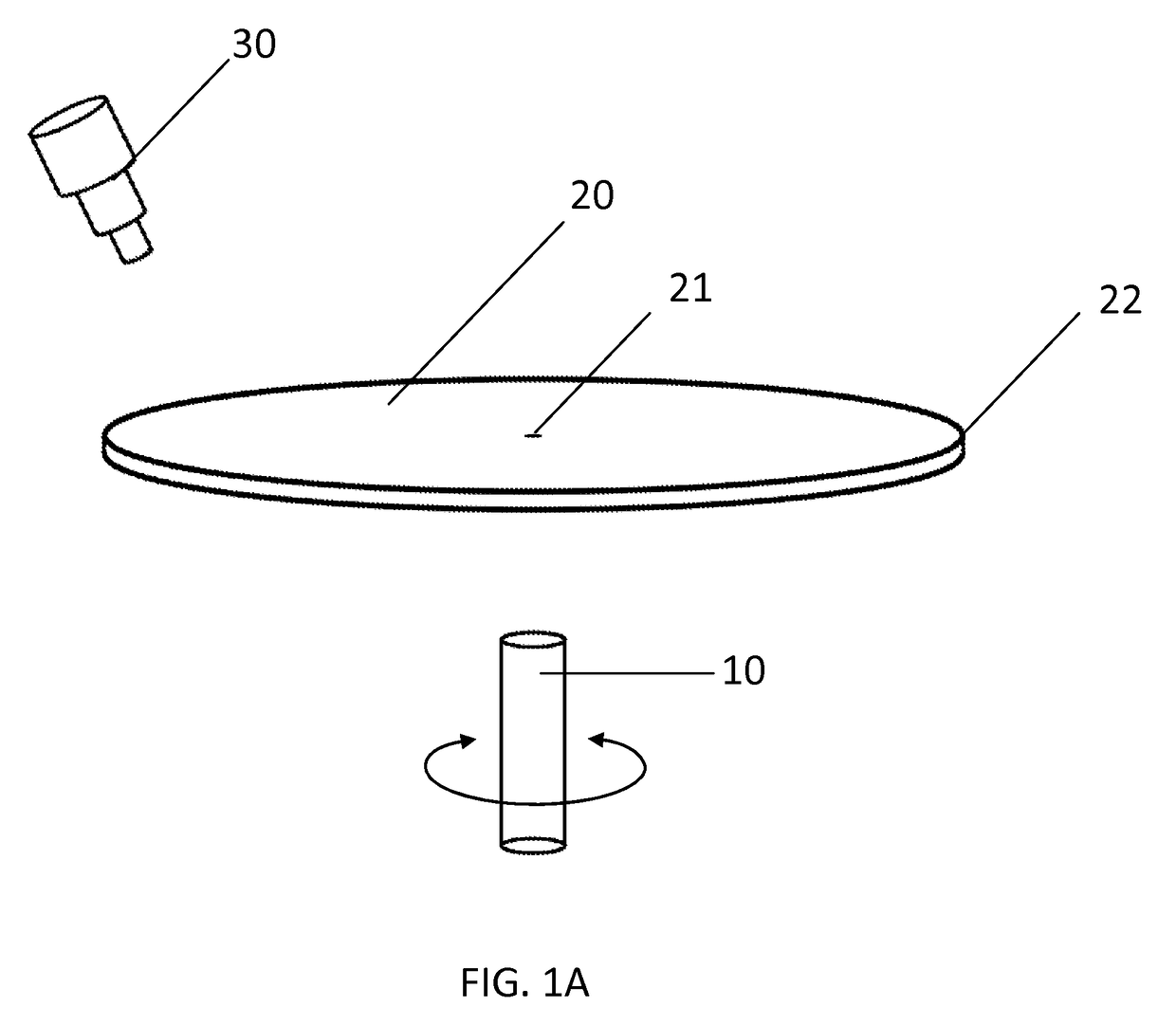
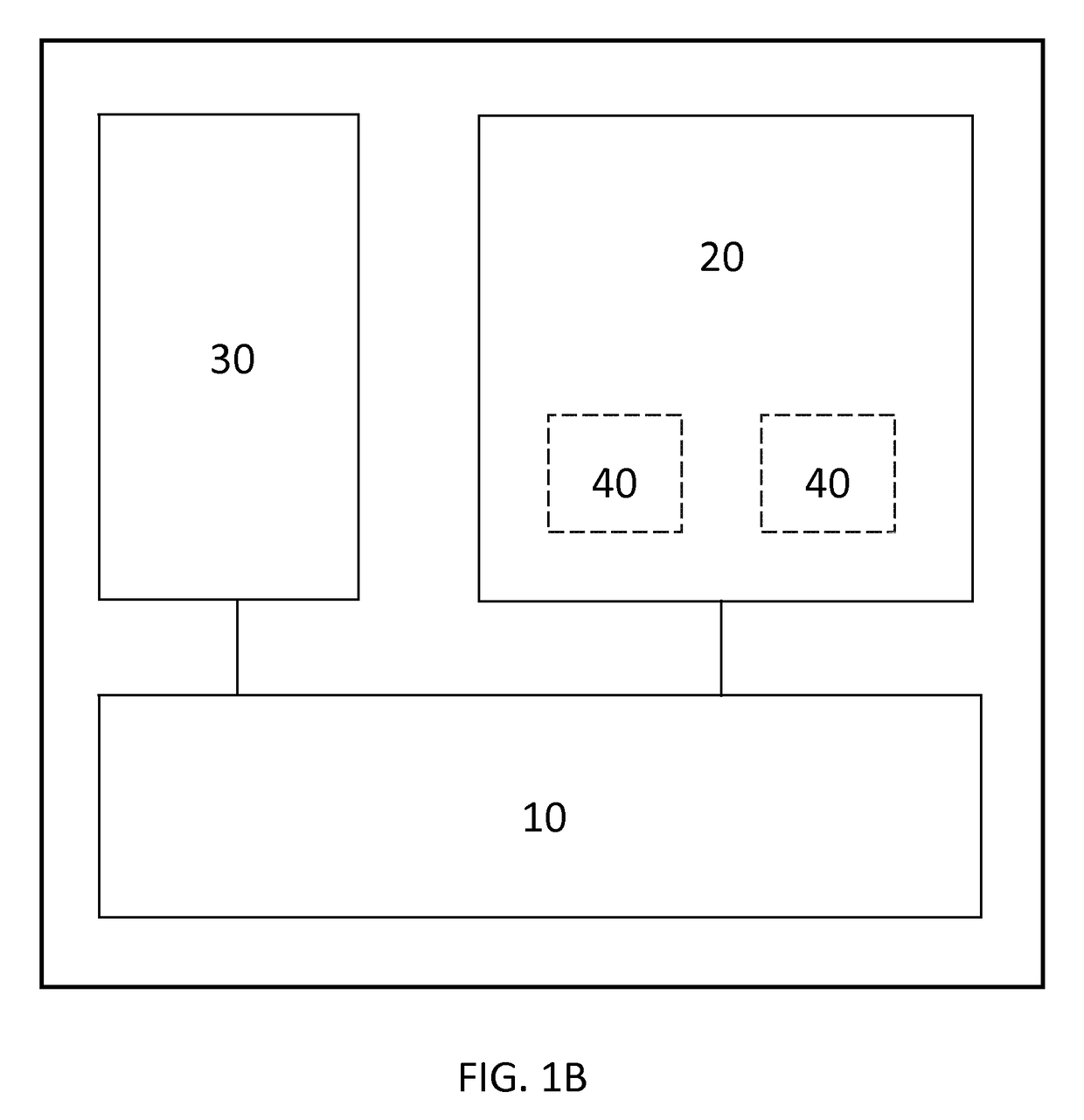
[0039]At least one embodiment of the present invention relates to a gas-based microfluidic device comprising a drive module and a microfluidic platform. The drive module is configured to drive and control the microfluidic platform to rotate, while the microfluidic platform is configured for solution preparation and solution metering. The microfluidic platform is mounted on the drive module, and comprising a center of rotation and at least one microfluidic element. Each microfluidic element further comprises an injection chamber, a process chamber, an air chamber, an overflow channel, a barrier, and at least one detection chamber.

[0040]FIG. 1A is a schematic diagram illustrating a gas-based microfluidic device, according to some embodiments of ...


PUM

PropertyMeasurementUnit
distanceaaaaaaaaaa
rotational speedaaaaaaaaaa
densityaaaaaaaaaa

Abstract

Gas-based microfluidic devices and operating methods of gas-based microfluidic devices are provided. The gas-based microfluidic devices comprise a drive module and a microfluidic platform, in which the microfluidic platform further comprises a microfluidic element having an injection chamber, a process chamber, an air chamber, an overflow channel, a barrier, and at least one detection chamber. Gases in the air chamber enable solutions to move toward the direction opposite to the centrifugal force applied by the drive module. Accordingly, the operating methods utilize the gases compressed in the air chamber to move solutions to difference components in the microfluidic element.

Description

CROSS-REFERENCE TO RELATED APPLICATION AND CLAIM OF PRIORITY[0001]This application claims the benefit of Chinese Patent Application No. 201410667532.0, filed on Nov. 20, 2014, in the State Intellectual Property Office of the People's Republic of China, the disclosure of which is incorporated herein in its entirety by reference.[0002]1. Technical Field[0003]At least one embodiment of the present invention relates to gas-based microfluidic devices and operating methods thereof. More particularly, the gas-based microfluidic devices and the operating methods are based on the utilizations of air pressure to transfer liquid.[0004]2. Description of the Related Art[0005]Sample preparation and solution metering are complex tasks in the art of analysis, in which both require well-trained technicians and advanced instruments to perform. Sample preparation and solution metering play a central role in obtaining qualified samples for analysis. However, costs on training technicians and purchasing...

Claims


Application Information

Patent Timeline
Patent Type & Authority Patents(United States)
IPC IPC(8): B01L3/00G01N21/07G01N33/53B01J19/00
CPCB01L3/502738B01L3/5027B01L3/50273B01L3/502723B01L3/502753B01L2200/0605B01L2200/0621B01L2300/0803B01L2400/0409B01L2400/06B01L2400/0688
Inventor LIN, CHIA-HUIYU, BOYANG, YI-FENG
Owner ZHEJIANG PUSHKANG BIOTECHNOLOGY CO LTD
Learn More