
Detection of radiation quanta using an optical detector pixel array and pixel cell trigger state sensing circuits

a technology of radiation quanta and detector pixel array, which is applied in the field of detection of radiation quanta, can solve problems such as errors, and achieve the effects of reliable determination of gamma photon energy, fast recovery time, and high optical photon incidence ra

Active Publication Date: 2017-06-13
KONINKLJIJKE PHILIPS NV
View PDF17 Cites 9 Cited by
  • Summary
  • Abstract
  • Description
  • Claims
  • Application Information

AI Technical Summary

Benefits of technology

The invention provides a new way to measure the number of optical photons detected by a device. Instead of using a composite avalanche current, the device uses predetermined signal amplitudes for each pixel cell. This results in a more reliable and repeatable integration of the number of optical photons and a more reliable timing signal. This invention is useful for improving the accuracy and resolution of imaging systems, particularly PET imaging systems.

Problems solved by technology

Such rejected events may be the consequence of gamma photon scattering; a phenomenon which changes the gamma photon trajectory as well as its energy and therefore leads to an erroneous LOR.

Method used


Image

  • Detection of radiation quanta using an optical detector pixel array and pixel cell trigger state sensing circuits
  • Detection of radiation quanta using an optical detector pixel array and pixel cell trigger state sensing circuits
  • Detection of radiation quanta using an optical detector pixel array and pixel cell trigger state sensing circuits

Examples


first embodiment

[0045]In the present invention a different approach is taken to the integration and the generation of a timing trigger signal. FIG. 4 illustrates aspects of the invention in which a pixel cell circuit 60, a radiation detection device 61 and a current waveform 62 are shown. With reference to FIG. 4, in the present invention a pixel cell trigger state sensing circuit 63 is configured to generate a digital signal (Isp) having either a first predetermined amplitude indicative of a triggered pixel cell or a second predetermined amplitude indicative of a non-triggered pixel cell. In the pixel cell trigger state sensing circuit 63 illustrated in FIG. 4 the digital signal is a digital current signal that is generated at first output 64. It will be appreciated however that alternative embodiments in which the digital signal is either a digital charge signal comprising a discrete packet of charge, or a digital voltage signal are also within the scope of the disclosure.

[0046]In the embodiment ...

second embodiment

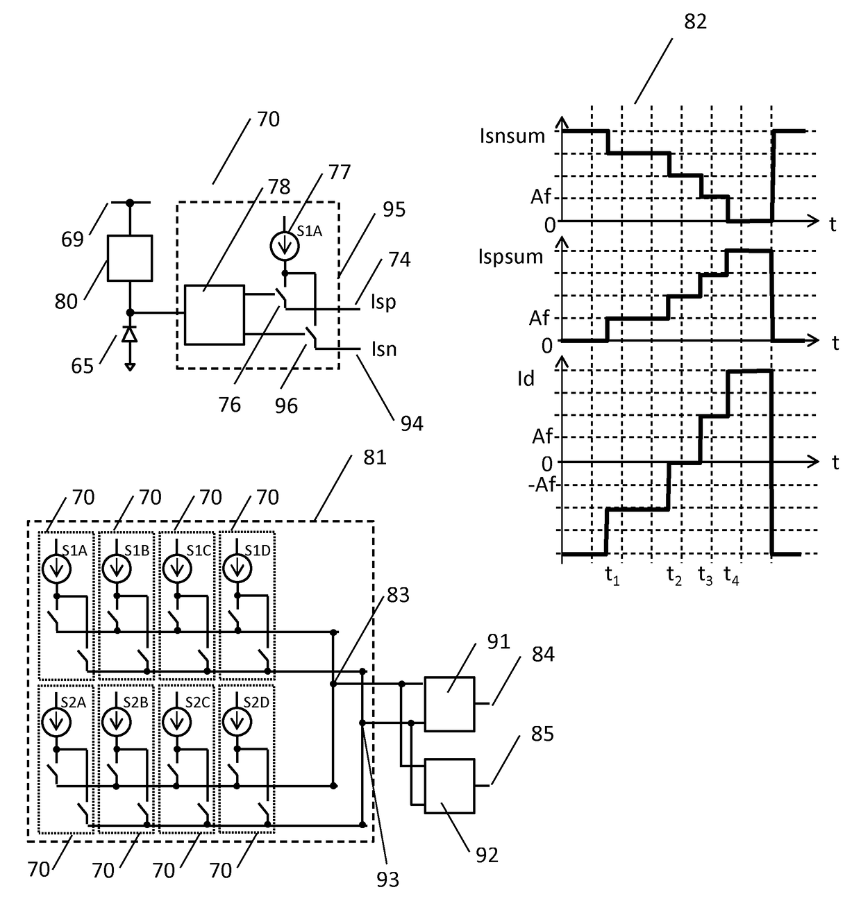
[0054]FIG. 5 illustrates aspects of the invention in which a pixel cell circuit 70, a radiation detection device 81 and current waveforms 82 are shown. FIG. 5 illustrates a development of the circuit illustrated in FIG. 4 which addresses non-linearity issues often encountered in current switches such as switch 66 illustrated in FIG. 4. With reference to pixel cell circuit 70 in FIG. 5, each current source has two outputs, a first output 74 which generates a signal (Isp), and a second output 94 which generates a signal (Isn). First output 74 operates in the same way as output 64 in FIG. 4, thus when avalanche photodiode 65 is in a non-triggered state, switch 76 is in a non-conductive state such that current source 77 is disconnected from first output 74 and consequently the digital current signal generated at first output 74 has a second predetermined amplitude. When an optical photon is received by avalanche photodiode 65, avalanche photodiode 65 transitions into a triggered state i...


PUM


Abstract

A radiation detection device integrates the number of optical photons in a light pulse. The radiation detection device includes an optical detector pixel array which has a plurality of pixel cells that are triggered by optical photons, a plurality of pixel cell trigger state sensing circuits, and a summing unit. Each pixel cell trigger state sensing circuit generates a digital signal having either a first predetermined amplitude indicative of a triggered pixel cell, or a second predetermined amplitude indicative of a non-triggered pixel cell. The summing unit generates an analog signal whose amplitude corresponds to the number of triggered pixel cells and thereby performs the integration. The analog signal may further cause a timing unit to generate a timestamp when a predetermined accumulated optical photon count condition is met.

Description

CROSS-REFERENCE TO PRIOR APPLICATIONS[0001]This application is the U.S. National Phase application under 35 U.S.C. §371 of International Application No. PCT / IB2014 / 056633, filed on Apr. 3, 2014, which claims the benefit of European Patent Application No. 13165097.0, filed on Apr. 24, 2013. These applications are hereby incorporated by reference herein.FIELD OF THE INVENTION[0002]The present invention relates to the detection of radiation quanta and finds application in high energy particle physics applications and in microscopy. Such applications encompass the direct detection of radiation quanta in the form of optical photons in fluorescence microscopy and from Cherenkov radiation, as well as the indirect detection of radiation quanta by means of the optical photons produced by a scintillator element. The invention finds particular application in PET imaging systems and in fluorescence lifetime imaging microscopy (FLIM), and even more particularly the invention can be used in time-...

Claims


Application Information

Patent Timeline
Patent Type & Authority Patents(United States)
IPC IPC(8): G01T1/20G01J1/44G01T1/208G01T1/24G01T1/00
CPCG01J1/44G01T1/00G01T1/208G01T1/2018G01T1/248G01T1/20183G01T1/20185G01T1/20184G01T1/20182H04N25/773
Inventor SHABER, MEZBAH UDDIN
Owner KONINKLJIJKE PHILIPS NV
Learn More