
Method for designing a modulated metasurface antenna structure

a modulated metasurface and antenna technology, applied in the direction of polarised antenna unit combinations, antennas, electrical devices, etc., can solve the problems of limited range of antenna configurations and performances that are achievable in the context of conventional antenna design, large bulky structure, complex and expensive manufacturing,

Active Publication Date: 2017-06-20
EUROPEAN SPACE AGENCY
View PDF3 Cites 1 Cited by
  • Summary
  • Abstract
  • Description
  • Claims
  • Application Information

AI Technical Summary

Benefits of technology

[0018]Embodiments of the present application are designed to overcome the limitations of the prior art discussed above. Embodiments of the present application provide a flexible method for designing a metasurface. Embodiments of the present application also provide a method for designing a metasurface that is applicable to generic desired antenna beams. Further, embodiments of the present application provide a method for designing a metasurface that provides control of a polarization of the antenna beam. Additionally, embodiments of the present application provide a method for designing a metasurface that allows designing metasurfaces for general antenna geometries and feed arrangements.

Problems solved by technology

The main limitations of the conventional approach are that the guiding and scattering properties of the materials used in the design are generally input parameters of the design procedure.
As a result, the range of antenna configurations and performances that are achievable in the context of conventional antenna design is limited.
This however leads to a much bulkier structure which is also rather complex and expensive to manufacture.
At the same time, the control afforded by the corrugated walls is limited by the fact that it is only known in the prior art how to design an axially symmetric structure with radial corrugations and a longitudinal modulation of width an depth, or an axially symmetric structure with axial corrugations and a radial modulation.
The use of artificial modulated surfaces (metasurfaces) allows for a radical departure from the conventional design procedure by providing extensive control of the impedance or scattering characteristics of the surface, however, at the cost of a rather complex design procedure.
However, the above examples of applications of metasurfaces in the prior art are limited to small antennas and do not feature any modulation of the metasurface itself.
The main reason for these limitations is a lack of a robust design procedure for the modulation of the metasurface.
One of the main limitations of this approach lies in the fact that the field matching on the impedance surface makes it difficult to control complex radiation pattern cases as well as complex modulation patterns.
In consequence, this prior art approach does not provide direct feedback on options concerning patch design.
Thus, if it is desired to use a different patch design, this different patch design has to be implemented by trial and error.
As it further turns out, the approach does not offer measures for avoiding undesired discontinuities that occur in the surface currents (mainly in the phase thereof) and thus occur also in the derivative of the tensorial surface impedance.
Lastly, the approach has a limited allowance for performing an optimum selection of the geometric parameters of the patches.
Accordingly, the approach does not allow for satisfying secondary requirements such as smoothness of the derivative of the wavevector, which could contribute to minimizing modal conversion and thus to improving the behavior of the impedance surface.
All of the above prior art approaches to designing the modulation of a metasurface are limited in that they are particularly adapted to a particular type of surface structure, e.g., a particular type of printed metal patch, to a design of the feed producing the electromagnetic wave launched on the metasurface, and moreover require knowledge of the desired electromagnetic field projected on the metasurface.
Modulation patterns that are obtainable by the above prior art approaches are rather limited, and more complex modulation patterns going beyond, e.g., a sine or cosine dependence of the modulation are not feasible.
Moreover, as indicated above also the complexity of radiated fields both with regard to spatial variation and polarization is limited.
Summarizing, presently known design procedures for metasurfaces are specific to the particular implementation of the metasurface and moreover offer little flexibility in adapting to different requirements.
Since the range of obtainable modulation patterns is limited, in principle also the range of configurations of the antenna beams scattered by the respective metasurfaces is limited to rather simple configurations, especially with regard to polarization and / or angular variation of the antenna beam.

Method used


Image

  • Method for designing a modulated metasurface antenna structure
  • Method for designing a modulated metasurface antenna structure
  • Method for designing a modulated metasurface antenna structure

Examples


Embodiment Construction

[0056]Preferred embodiments of the present application will be described in the following with reference to the accompanying figures, wherein in the figures, identical objects are indicated by identical reference numbers. It is understood that the present application shall not be limited to the described embodiments, and that the described features and aspects of the embodiments may be modified or combined to form further embodiments of the present application.

[0057]The present application relates to a conjugate-matched design procedure for obtaining artificial surface antennas with modulated scattering tensor (modulated impedance tensor).

[0058]In the context of the present application, modulated metasurface antennas are based on the use of a special type of scattering surfaces characterized by a modulation of their scattering tensor. The surface, which can be flat or curved or faceted, is illuminated by one or more feeding elements (either embedded or external). Several surfaces ca...


PUM


Abstract

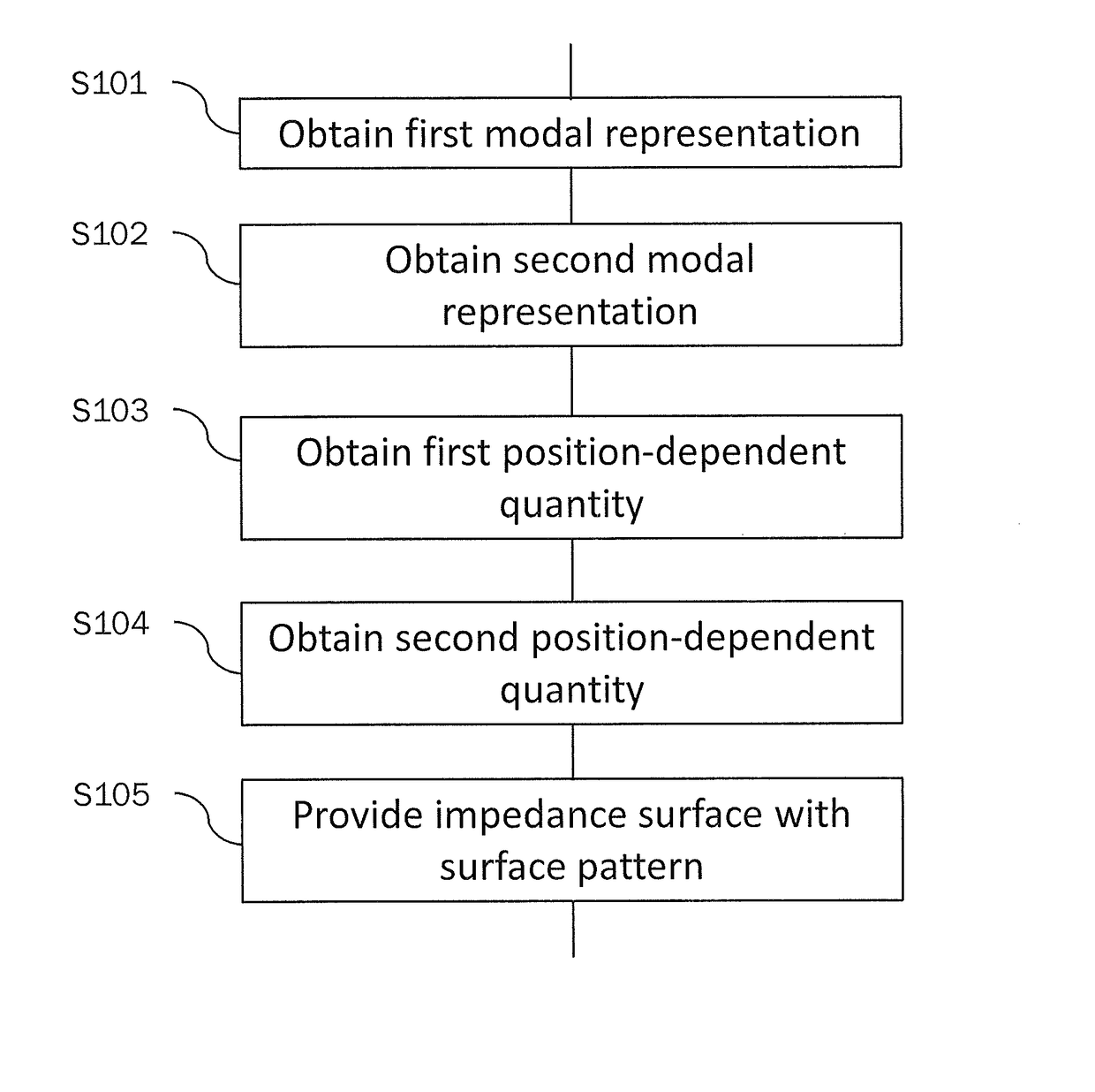
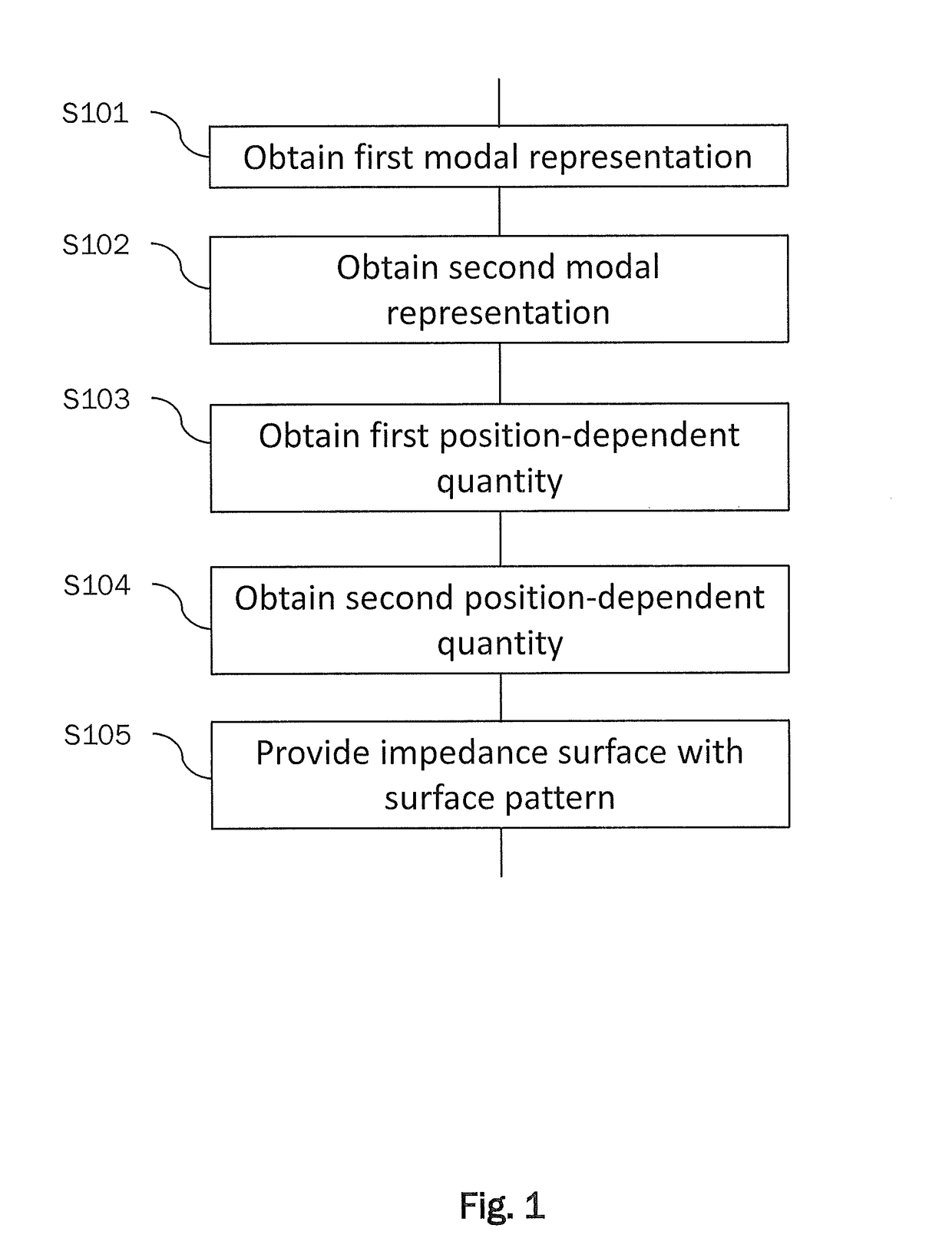
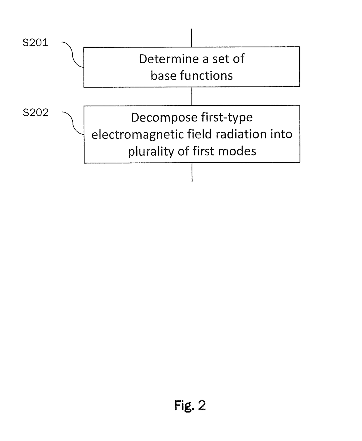
A method for designing a surface pattern for an impedance surface which results in a position-dependent target impedance of said impedance surface, and the impedance surface having the position-dependent target impedance radiates a desired first-type electromagnetic field radiation in reaction to being irradiated by a second-type electromagnetic field radiation. The method includes obtaining a first modal representation on the basis of the first-type electromagnetic field radiation in terms of a set of base modes that are chosen in accordance with a model function of the position-dependent target impedance, and obtaining a second modal representation on the basis of the second-type electromagnetic field radiation and the model function in terms of the set of base modes. The method further includes obtaining a first position-dependent quantity indicative of the position-dependent target impedance on the basis of the first modal representation and the second modal representation by determining values for a plurality of parameters of the model function for maximizing an overlap between the first modal representation and the second modal representation, and obtaining, as the surface pattern, a second position-dependent quantity indicative of geometric characteristics of the impedance surface on the basis of the first position-dependent quantity and a relationship between geometric characteristics of the impedance surface and corresponding impedance values.

Description

BACKGROUND[0001]Technical Field[0002]The present application relates to a method for designing a modulated metasurface antenna. More particularly, the present application relates to designing a surface pattern for a modulated metasurface antenna, i.e., to designing a surface pattern for an impedance surface which, if provided on said impedance surface, results in a position-dependent target impedance of said impedance surface, and the impedance surface having the position-dependent target impedance radiates a desired electromagnetic field radiation in reaction to being irradiated by given electromagnetic field radiation. The present application further relates to an impedance surface having a surface pattern designed by the inventive method and to an antenna provided with an impedance surface having a surface pattern designed by the inventive method.[0003]The disclosure in the present application is particularly though not exclusively applicable to designing impedance surfaces for m...

Claims


Application Information

Patent Timeline
Patent Type & Authority Patents(United States)
IPC IPC(8): H01Q15/00H01Q21/24
CPCH01Q15/0066H01Q15/00H01Q21/24
Inventor SABBADINI, MARCOMINATTI, GABRIELEMACI, STEFANOPATRIZIO DE VITA, PAOLO
Owner EUROPEAN SPACE AGENCY
Learn More