Fuel deoxygenation and fuel tank inerting system and method

a fuel tank and deoxygenation technology, applied in liquid degasification, separation of dispersed particles, separation processes, etc., can solve the problems of limiting the ability of fuel to absorb heat beyond, increasing maintenance, and reducing the performance of fuel systems, so as to improve aircraft specific fuel consumption.

Active Publication Date: 2017-06-27
HONEYWELL INT INC
View PDF98 Cites 40 Cited by
  • Summary
  • Abstract
  • Description
  • Claims
  • Application Information

AI Technical Summary

Problems solved by technology

The presence of molecular oxygen or entrained air limits the ability of fuel to absorb heat beyond approximately 300° F. without undergoing deleterious thermal degradation.
Thermal degradation often appears as solid materials which adhere to surfaces and degrades fuel system performance increase.
However, these often use equipment that is subject to fouling, which can lead to increased maintenance, and / or process steps that are difficult to control.

Method used


Image

  • Fuel deoxygenation and fuel tank inerting system and method
  • Fuel deoxygenation and fuel tank inerting system and method
  • Fuel deoxygenation and fuel tank inerting system and method

Examples


Embodiment Construction

[0014]The following detailed description is merely exemplary in nature and is not intended to limit the invention or the application and uses of the invention. As used herein, the word “exemplary” means “serving as an example, instance, or illustration.” Thus, any embodiment described herein as “exemplary” is not necessarily to be construed as preferred or advantageous over other embodiments. All of the embodiments described herein are exemplary embodiments provided to enable persons skilled in the art to make or use the invention and not to limit the scope of the invention which is defined by the claims. Furthermore, there is no intention to be bound by any expressed or implied theory presented in the preceding technical field, background, brief summary, or the following detailed description.

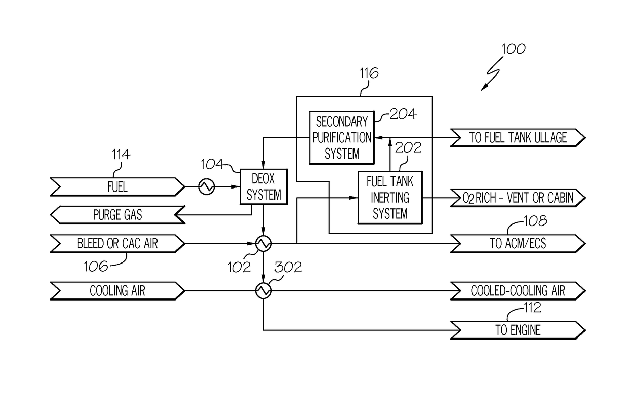
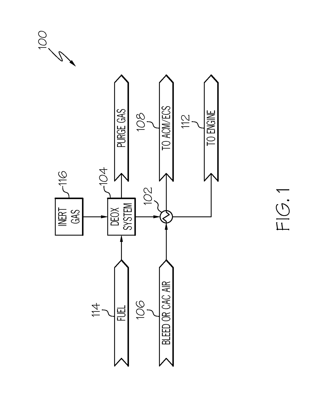
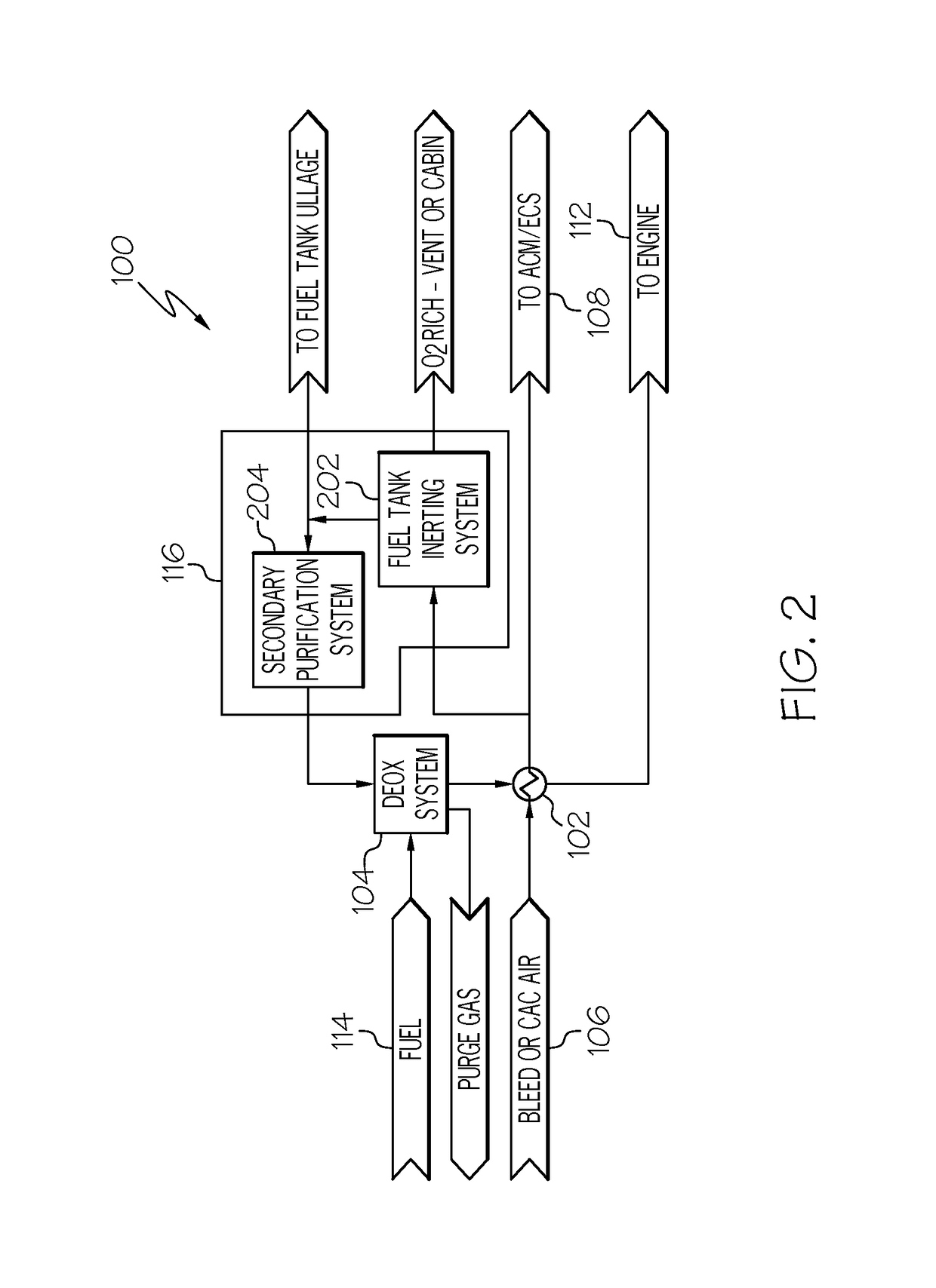
[0015]Referring first to FIGS. 1-3, embodiments of an integrated deoxygenation and fuel inerting system 100 is depicted. Each of the depicted systems 100 includes an air / fuel heat exchanger 102...


PUM

PropertyMeasurementUnit
temperatureaaaaaaaaaa
concentrationaaaaaaaaaa
drive torqueaaaaaaaaaa

Abstract

An aircraft fuel deoxygenation and tank inerting system includes an inert gas source, a fuel deoxygenation system, and an air / fuel heat exchanger. The inert gas source is configured to supply inert gas having an oxygen concentration of less than 3%. The fuel deoxygenation system is adapted to receive fuel from a fuel source and the inert gas from the inert gas source. The fuel deoxygenation system is configured to remove oxygen from the fuel and thereby generate and supply deoxygenated fuel and oxygen-rich purge gas. The air / fuel heat exchanger is adapted to receive compressed air from a compressed air source and the deoxygenated fuel from the fuel deoxygenation system. The air / fuel heat exchanger is configured to transfer heat from the compressed air to the deoxygenated fuel, to thereby supply cooled compressed air and heated deoxygenated fuel.

Description

CROSS-REFERENCE TO RELATED APPLICATION[0001]This application claims the benefit of U.S. Provisional Application No. 61 / 986,464, filed Apr. 30, 2014.TECHNICAL FIELD[0002]The present invention generally relates to fuel deoxygenation, and more particularly relates to systems and methods for deoxygenating fuel and, in some embodiments, inerting fuel tanks.BACKGROUND[0003]Modern aircraft rely on efficient heat sink options for thermal management. The jet fuel that is supplied to the propulsion engines is often a convenient sink for excess thermal energy, and the energy is efficiently retained in the engine thermodynamic cycle. The presence of molecular oxygen or entrained air limits the ability of fuel to absorb heat beyond approximately 300° F. without undergoing deleterious thermal degradation. Thermal degradation often appears as solid materials which adhere to surfaces and degrades fuel system performance increase. Moreover, wetted surfaces comprised of metallic materials can further...

Claims


Application Information

Patent Timeline
Patent Type & Authority Patents(United States)
IPC IPC(8): B01D19/00B01D53/047B01D53/22B01D53/86
CPCB01D53/047B01D19/0005B01D19/0026B01D53/225B01D2258/06B01D53/229B01D53/864B01D2053/221B01D2256/10B01D2257/104B01D2257/702
Inventor JOHNSON, RUSSELL W.MICHALAKOS, PETER MBLUMER, ERICBERSHITSKY, ALEXANDERLO, CHARLES
Owner HONEYWELL INT INC
Why Eureka
Try Eureka