

Method for cleaning surfaces
- Summary
- Abstract
- Description
- Claims
- Application Information
AI Technical Summary
Benefits of technology
Problems solved by technology
Method used
Image

Examples
first embodiment
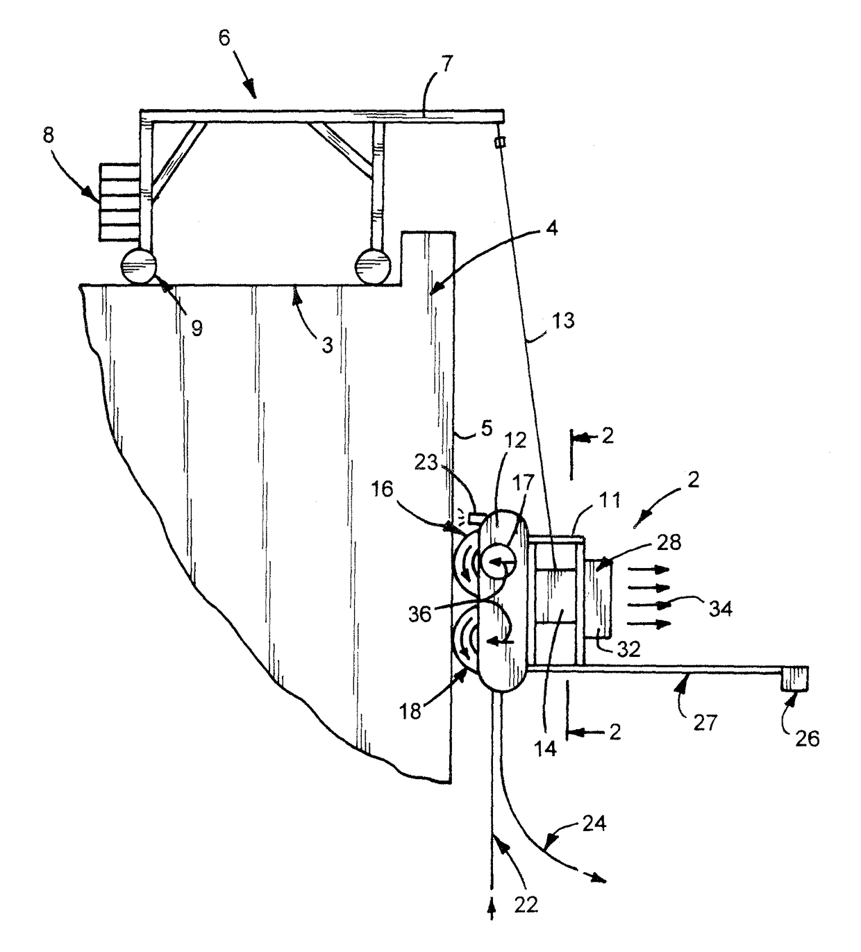
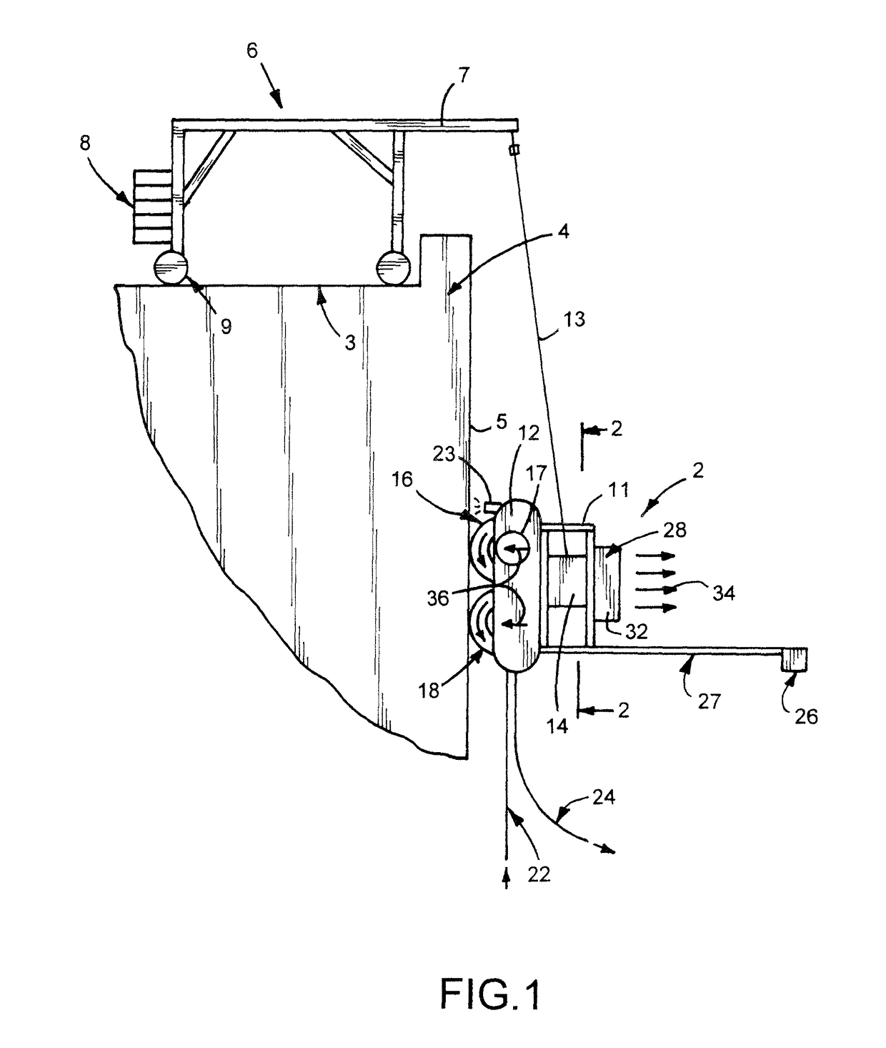
[0042]the cleaning apparatus 2, shown in FIGS. 1 to 3, pendently supported adjacent the outside of a building 4 is operable to cleaning the outside wall or windows 5. A support or davit 6 located on the building's roof 3 has a generally horizontal arm 7 extended outwardly from the top of building 4. A plurality of counterweights 8 mounted on the inner end of davit 6 maintain arm 7 in a generally horizontal position and counter the weight of cleaning apparatus 2 connected thereto with a cable 13. The upper end of cable 13 is secured to the outer end of arm 7. Davit 6 has wheels 9 that permit movement of davit 6 along roof 3 during cleaning of wall 5. Other types of davits can be used to pendently support cleaning apparatus adjacent the side of a building or an upright structure.
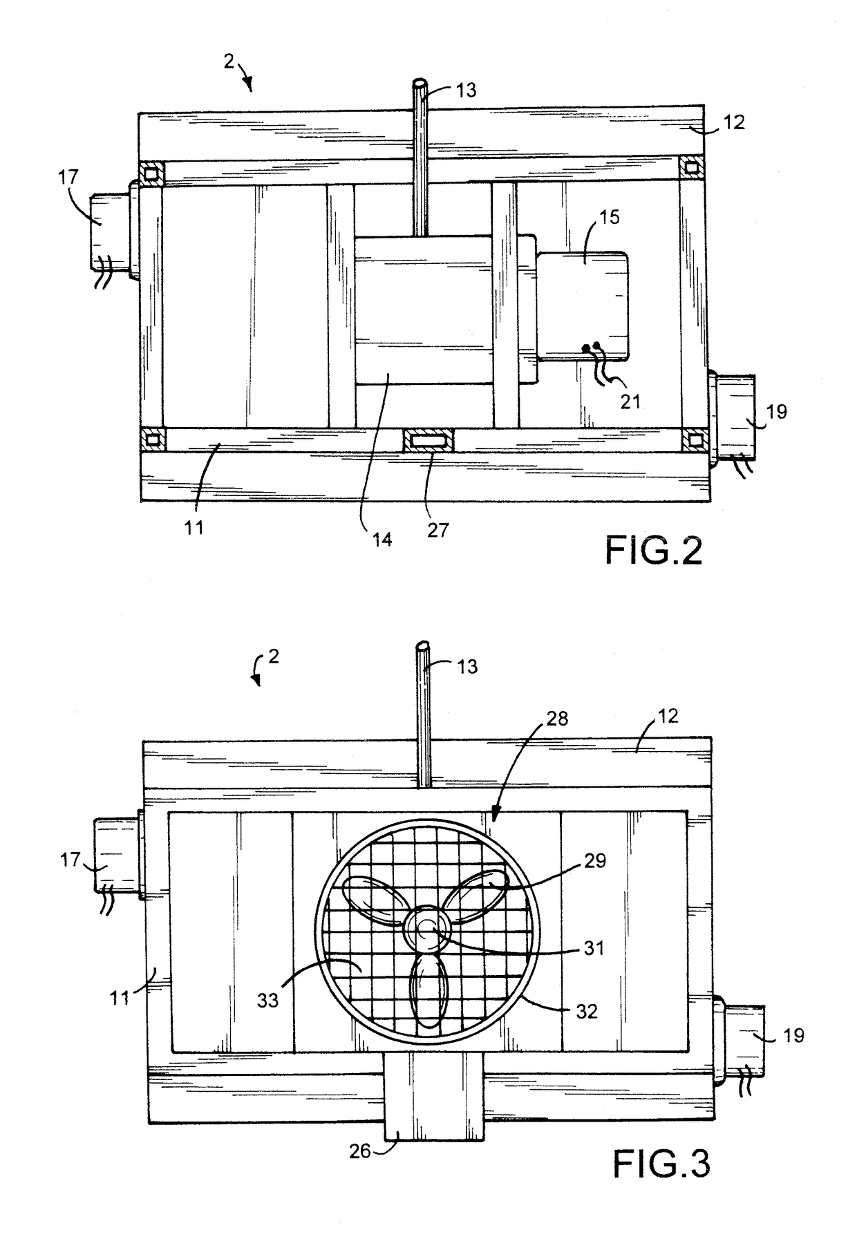
[0043]Cleaning apparatus 2 has a frame 11 having horizontal and vertical interconnected members or beams. A housing or shield 12 is secured to frame 11. Shield 12 has a back wall and side walls with an opening...
second embodiment
[0050]the cleaning apparatus 100, shown in FIGS. 4 to 6, pendently supported adjacent the outside of a building 101 is operable to cleaning the outside wall or windows. A support or davit 103 located on the building's roof 109 has a generally horizontal arm 104 extended outwardly from the top of building 101. A plurality of counterweights 108 mounted on the inner end of davit 193 maintain arm 104 in a generally horizontal position and counter the weight of cleaning apparatus 100 connected thereto with a cable 111. The upper end of cable 111 is secured to the outer end of arm 104. Davit 103 has wheels 106 and 107 that permit movement of davit 103 along roof 109 during cleaning of wall 102. Other types of davits can be used to pendently support cleaning apparatus adjacent the side of a building or an upright structure.
[0051]Cleaning apparatus 100 has a frame 112 having horizontal and vertical interconnected members or beams. A housing or shield 113 is secured to frame 112. Shield 113 ...
third embodiment
[0057]the cleaning apparatus 300, shown in FIGS. 11 to 14, is pendently supported with a cable 306 from a davit located on a building. Cleaning apparatus 300 has a frame 301 comprising horizontal frame members 302 and 303 connected to upright frame members 304 and 305. An arcuate shield 307 secured to frame member 302 is located adjacent an inside circumferential portion of a cleaning element or brush 308. Brush 308 has a plurality of outwardly extended vanes 309 mounted on a cylindrical body 311. The structure of brush 117 shown in FIGS. 8 and 9 is the same as brush 308. Brush 308 is rotatably mounted for rotation about a horizontal axis on bearings 312 and 313 secured to upright members 304 and 305. An electric motor 314 drives a power transmission or gear box 316 operatively connected to brush 308 whereby on operation of motor 314 brush is rotated.
[0058]A liquid applicator 317 mounted on frame member 302 above brush 308 operates to dispense cleaning liquid onto the surface to be ...
PUM
 Abstract
Description
Claims
Application Information