Boss for composite container

a composite container and boss technology, applied in the direction of vessel construction details, container discharge methods, mechanical devices, etc., to achieve the effect of not expensive production

Active Publication Date: 2017-06-27
HEXAGON RAGASCO AS
View PDF23 Cites 4 Cited by
  • Summary
  • Abstract
  • Description
  • Claims
  • Application Information

AI Technical Summary

Benefits of technology

[0009]It is an object of the present invention to provide a boss suitable for use in composite pressure containers holding fluids of not only relatively low pressures, but which can also be used on pressure containers holding fluids of higher pressures, and which boss is not expensive to produce.
[0010]The pressure, temperature or concentration differences over the boss materials may cause permeation of fluid through the materials. This is especially relevant in connection with sealings such as O-rings and sealing surfaces. If a boss comprises an environmental O-ring, or a gas tight sealing such as a gas tight threaded connection or another type of connection above (axially outside of), the inner main sealing pressure can build up within the boss in between the main sealing the additional gas tight sealing. Build up of internal pressure within the boss can influence the safety and proper functioning of the boss.
[0011]Another object of the present invention is therefore to assure that any fluid under pressure that may permeate through the sealing or the materials of the sealing surfaces of a boss is inhibited from building up pressure within the boss. Equivalently any leakage including thermal induced leakage is inhibited from resulting in pressure built up within the boss.
[0012]A further object of the present invention is to provide a boss with long durability also at high pressures, thereby allowing the container to be reused many times and reducing costs.

Problems solved by technology

Additionally, the boss construction may be influenced by an axially inward directed force, e.g., when a valve or coupling member is mounted to the boss, and possibly by unintended stress caused by impacts or blows.

Method used


Image

  • Boss for composite container
  • Boss for composite container
  • Boss for composite container

Examples


Embodiment Construction

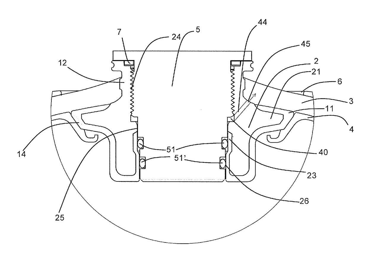
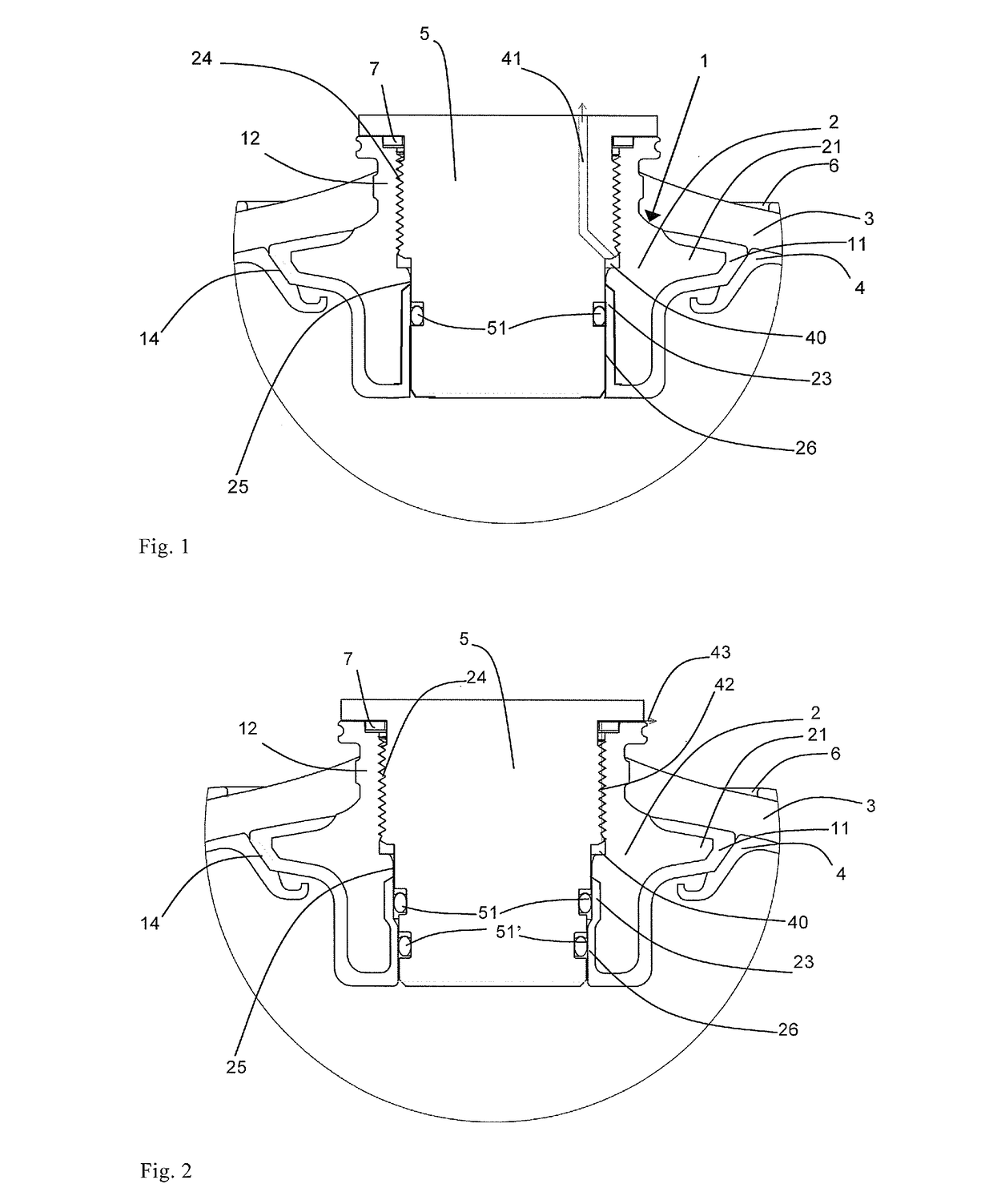
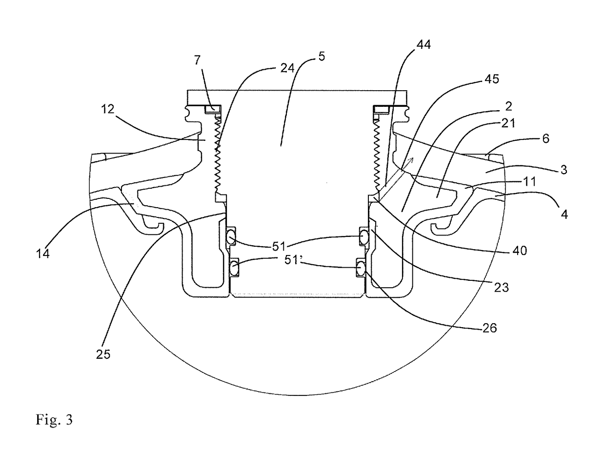
[0024]FIGS. 1, 2 and 3 illustrate three alternative embodiments of different aspects of the present invention. All the figures show a boss 1 on a pressure container, wherein the boss comprises an opening, and a coupling or valve member 5 is fitted in the opening. The boss 1 is welded, glued, casted, molded, or in another way fixed to an inner liner layer 4 on the composite pressure container with a connecting flange 11. The connecting flange is fixed to the liner layer 4 through an inclined surface 14. As mentioned above, the fixation may be carried out in a known way by welding, by different gluing techniques, or by other techniques, depending on the materials used. Alternatively, to the solution shown, the boss is an integrated part of the liner layer or the liner layer may be melted together with the connecting flange to form a continuous surface toward the opening, or the liner forms an integrated flange where the boss is connected to the outside of the integrated liner flange p...


PUM

PropertyMeasurementUnit
pressureaaaaaaaaaa
pressureaaaaaaaaaa
pressureaaaaaaaaaa

Abstract

A composite pressure container for fluids includes a pressure container, a boss (1), and a coupling or valve member (5) fitted in an opening in the boss. The pressure container includes an inner fluid-tight liner layer (4) and a pressure supporting layer (3) formed by winding fiber-reinforcement onto the liner layer. The boss is positioned in a central opening of the pressure container. The structure of the boss comprises a depressurization passage for preventing build-up of internal pressure inside the boss.

Description

BACKGROUND OF THE INVENTION[0001]1. Technical Field[0002]The present invention relates to an improved boss for a composite pressure container. Especially, the present invention relates to a boss adapted to avoid internal pressure built up.[0003]This invention concerns an improved boss for a composite pressure container for fluids, wherein the container comprises an inner fluid-tight thermoplastic liner layer and a pressure supporting layer formed by winding fiber-reinforcement onto the liner layer, as well as at least one central aperture in at least one end, for provision of a boss for mounting a coupling or a valve member.[0004]2. Description of the Related Art[0005]A boss for composite pressure containers is disclosed in Norwegian Patent No. 312048. Composite pressure containers are disclosed in Norwegian Patent No. 306226 and 309667.[0006]Pressure containers like these are subject to numerous and varied types of stress and forces. Mainly, this regards the inner over pressure whi...

Claims


Application Information

Patent Timeline
Patent Type & Authority Patents(United States)
IPC IPC(8): F17C13/04F17C1/16F17C1/06
CPCF17C1/06F17C1/16F17C2201/0109F17C2201/056F17C2203/0604F17C2203/066F17C2203/0619F17C2203/0663F17C2205/0305F17C2205/0323F17C2205/0394F17C2209/2118F17C2209/2127F17C2209/227F17C2221/012F17C2221/033F17C2221/035F17C2223/0123F17C2223/0153F17C2223/035F17C2223/036F17C2260/021F17C2260/037F17C2260/042F17C2270/01Y02E60/321Y02E60/32
Inventor ULEKLEIV, RUNEHAMNVIK, PER VIDAR
Owner HEXAGON RAGASCO AS
Why Eureka
Try Eureka