Magnetic detection device and torque sensor including the same
- Summary
- Abstract
- Description
- Claims
- Application Information
AI Technical Summary
Benefits of technology
Problems solved by technology
Method used
Image

Examples
first embodiment
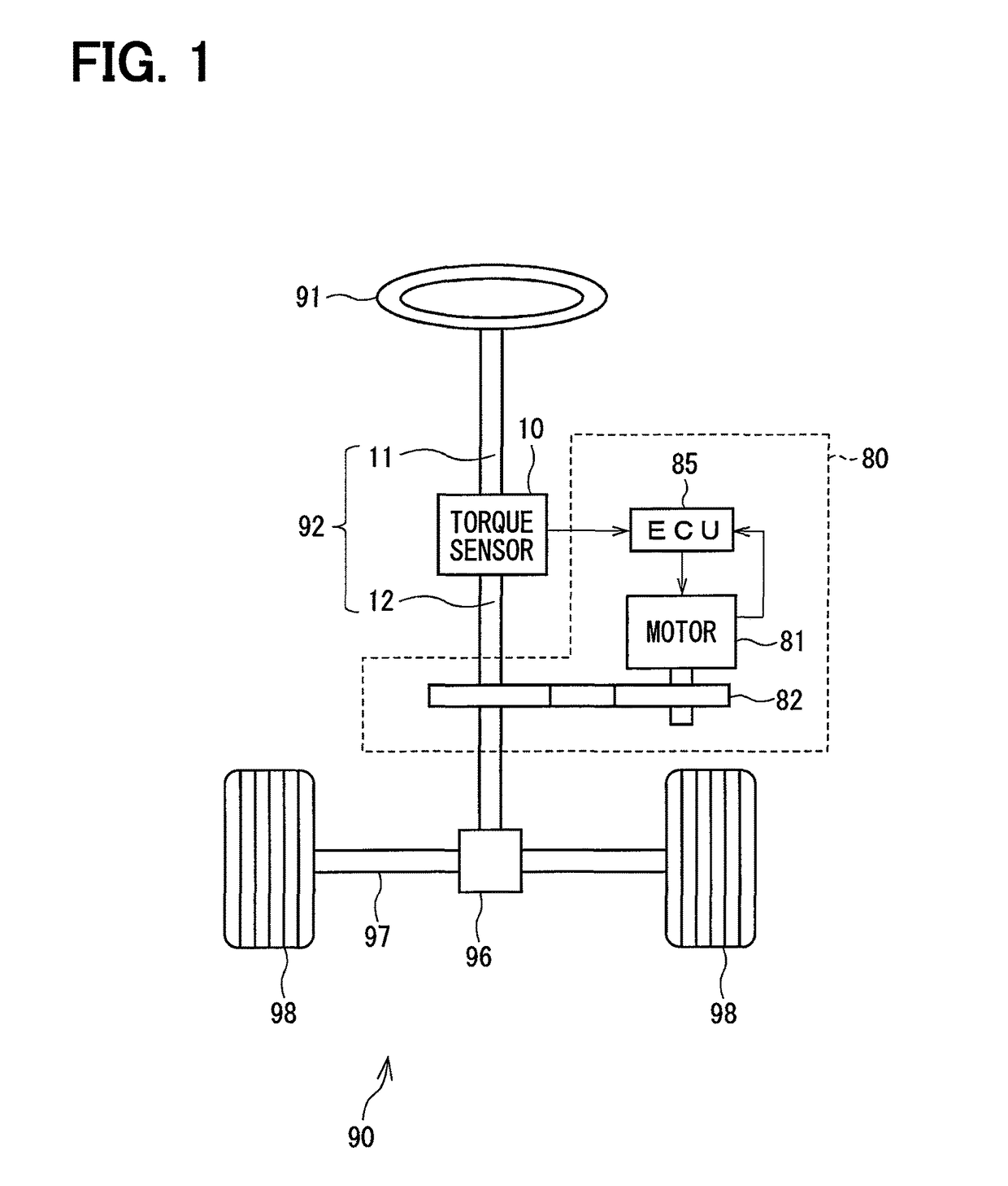
[0047]A first embodiment of the present disclosure is shown in FIGS. 1 to 20. Further, each figure is a schematic view, and the same applies to the figures of the later described embodiments. As shown in FIG. 1, a torque sensor 10 is applied to an electric power steering device 80 that assists a steering operation of, e.g., a vehicle.
[0048]FIG. 1 shows the overall configuration of a steering system 90 that includes the electric power steering device 80. Here, a steering shaft 92 is connected to a handle 91.
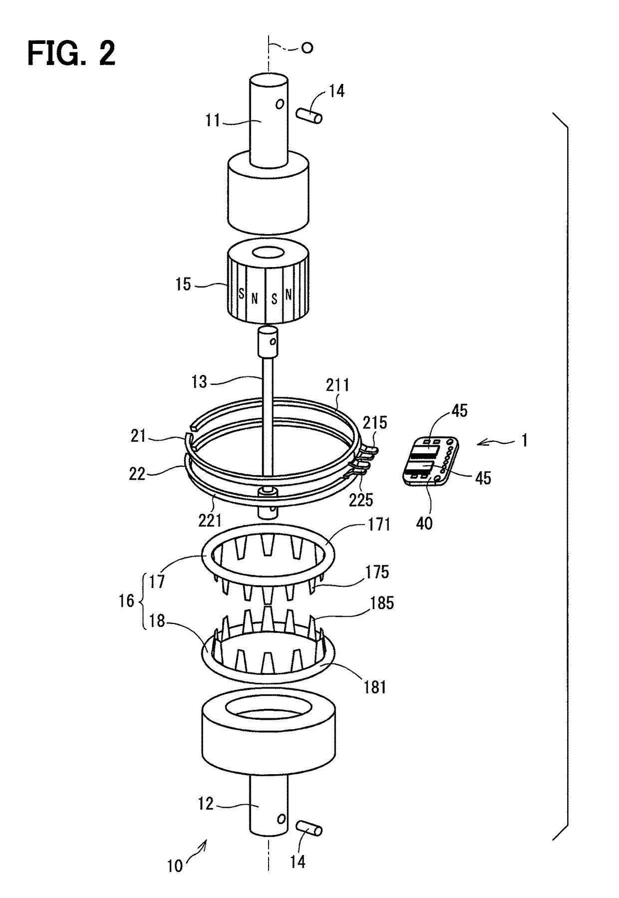
[0049]The steering shaft 92 includes an input shaft 11 that acts as a first shaft and an output shaft 12 that acts as a second shaft. The input shaft 11 is connected to the handle 91. The torque sensor 10, which detects a torque applied to the steering shaft 92, is disposed between the input shaft 11 and the output shaft 12. A pinion gear 96 is disposed at an end of the output shaft 12 away from the input shaft 11. The pinion gear 96 is geared with a rack shaft 97. The two ends of...
fifth embodiment
[0146]A fifth embodiment of the present disclosure is shown in FIG. 24. Here, FIG. 24 corresponds to FIG. 11 of the first embodiment. The same applies to FIGS. 25 to 27 which are described later.
[0147]As shown in FIG. 24, a collector ring retainer 125 of the present embodiment is formed from a non-magnetic material such as resin, and is divided into a first retainer member 126 and a second retainer member 127. The first collector ring 21 is embedded in the first retainer member 126, and the second collector ring 22 is embedded in the second retainer member 127.
[0148]As shown by the arrows Y2 in FIG. 24, in the present embodiment, the first retainer member 126 and the second retainer member 127 are assembled such that the first retainer member 126 approaches toward the front surface 451 of the magnetic sensors 45, while the second retainer member 127 approaches toward the rear surface 452 of the magnetic sensors 45, thereby surrounding the magnetic sensors 45. At that time, similar t...
sixth embodiment
[0153]The sixth embodiment of the present disclosure is shown in FIG. 25.
[0154]As shown in FIG. 25, in the present embodiment, the shapes of a first collector ring 610 and a second collector ring 620 are different from the above embodiments. Here, the first collector ring 610 acts as a first magnetic collector, and the second collector ring 620 act as a second magnetic collector. The collector rings 610, 620 are functionally the same as those of the above described embodiments. The same applies to a collector ring 650 which is described later.
[0155]The first collector ring 610 includes a ring portion 611, middle portions 612, and collector portions 615. The ring portion 611 is formed of a soft magnetic material, and is substantially ring shaped. The middle portions 612 protrude radially outward from the ring portion 611. The collector portions 615 are bent at the middle portions 612 from a direction away from the ring portion 611 to a direction toward the second collector ring 620. ...
PUM
 Abstract
Description
Claims
Application Information
 - R&D Engineer
- R&D Manager
- IP Professional
- Industry Leading Data Capabilities
- Powerful AI technology
- Patent DNA Extraction
Browse by: Latest US Patents, China's latest patents, Technical Efficacy Thesaurus, Application Domain, Technology Topic.
© 2024 PatSnap. All rights reserved.Legal|Privacy policy|Modern Slavery Act Transparency Statement|Sitemap