Motor drive device

a technology of motor drive and drive power supply, which is applied in the direction of electric motor speed/torque regulation, electric devices, transportation and packaging, etc., can solve the problems of increasing copper and achieve the effect of reducing the loss between the drive power source and the controller

Active Publication Date: 2017-06-27
NTN CORP
View PDF18 Cites 3 Cited by
  • Summary
  • Abstract
  • Description
  • Claims
  • Application Information

AI Technical Summary

Benefits of technology

[0008]An object of the present invention is to provide a motor drive device which is able to reduce loss between a drive power source and a controller.
[0012]According to this configuration of the invention, the phase shift portion 10a of the controller 8 shifts the PWM signal for causing a current to flow to the motor 4 such that the PWM signal has a phase different per motor, whereby averaging can be performed such that overlap of pulse-like currents in the same time is reduced. That is, the phase shift portion 10a shifts an energizing time during which a current is applied to one of the motors 4 and an energizing time during which a current is applied to the other motor 4, and thereby can suppress an increase in a current value in the waveform diagram in which the currents applied to the motors 4 are combined. As described above, so-called overlap of energizing times of currents can be avoided. Thus, loss on the energizing path L1 between the drive power source 7 and the controller 8 can be reduced. This is because the loss on the energizing path L1 is, for example, simply proportional to an energizing time, and is proportional to the square of a current value. Therefore, the loss between the drive power source 7 and the controller 8 can be reduced by the phase shift portion 10a shifting the energizing time during which a current is applied to the motor 4.
[0013]The motors 4 may be mounted on a vehicle. In this case, the loss between the controller 8 and the battery 7 which is a drive power source mounted on the vehicle can be reduced. Thus, it is possible to improve the electric mileage or the gas mileage of the vehicle to increase the maximum travel range of the vehicle.
[0014]The motors 4 may be configured to drive wheels of an electric vehicle 1. The motors 4 configured to drive the wheels have higher output than a motor for each electric device. In this case, the effect of reducing the loss between the battery 7 and the controller 8 increases, and thus it is possible to improve the electric mileage of the electric vehicle 1 to further increase the maximum travel range of the electric vehicle 1.
[0015]The phase shift portion 10a may set a shift time Δt for the phase of the PWM signal as Δt=tw / n which is obtained by dividing one cycle tw of the PWM signal by the number n of the motors 4 to be driven by the controller 8. By setting the shift time Δt for the phase and shifting an energizing time during which a current is applied to one of the motors 4 and an energizing time during which a current is applied to the other motor 4, as described above, averaging can be performed such that overlap of pulse-like currents in the same time is reduced. Since the phases can be shifted with a simple arithmetic equation as described above, the load of arithmetic processing can be reduced.
[0016]The controller 8 may include a single calculation unit or arithmetic unit 10, and switching elements 11a which are respectively connected to the plurality of motors 4 to be driven. In this case, the entire structure of the motor drive device can be simplified to reduce the manufacturing cost. The controller 8 may include a plurality of calculation units 10, and the controller 8 may include: normal-time drive control unit 21 configured to, when the plurality of calculation units 10 are in a normal state, drive the respective motors 4 with the corresponding PWM signals having different phases by the plurality of calculation units 10; and abnormal-time drive control unit 22 configured to, when any one calculation unit 10 of the plurality of calculation units 10 is in an abnormal state, drive the motor 4 that has been driven by the abnormal calculation unit 10, by another calculation unit 10. Even when it is determined that one of the calculation units 10 is in an abnormal state, the motors 4 can be driven by another normal calculation unit 10 that is not determined as being in an abnormal state. In this case, for example, a control system is more complicated than when the controller 8 includes a single calculation unit, but can have redundancy.

Problems solved by technology

When the plurality of motors are driven simultaneously by the PWM method with the single drive power source as described above, there is a problem that, as compared to the case where a drive power source is provided for each motor, copper loss between the drive power source and the controller increases as periods during which the respective motors are energized by the PWM driver overlap each other increasingly.

Method used


Image

  • Motor drive device
  • Motor drive device
  • Motor drive device

Examples


Embodiment Construction

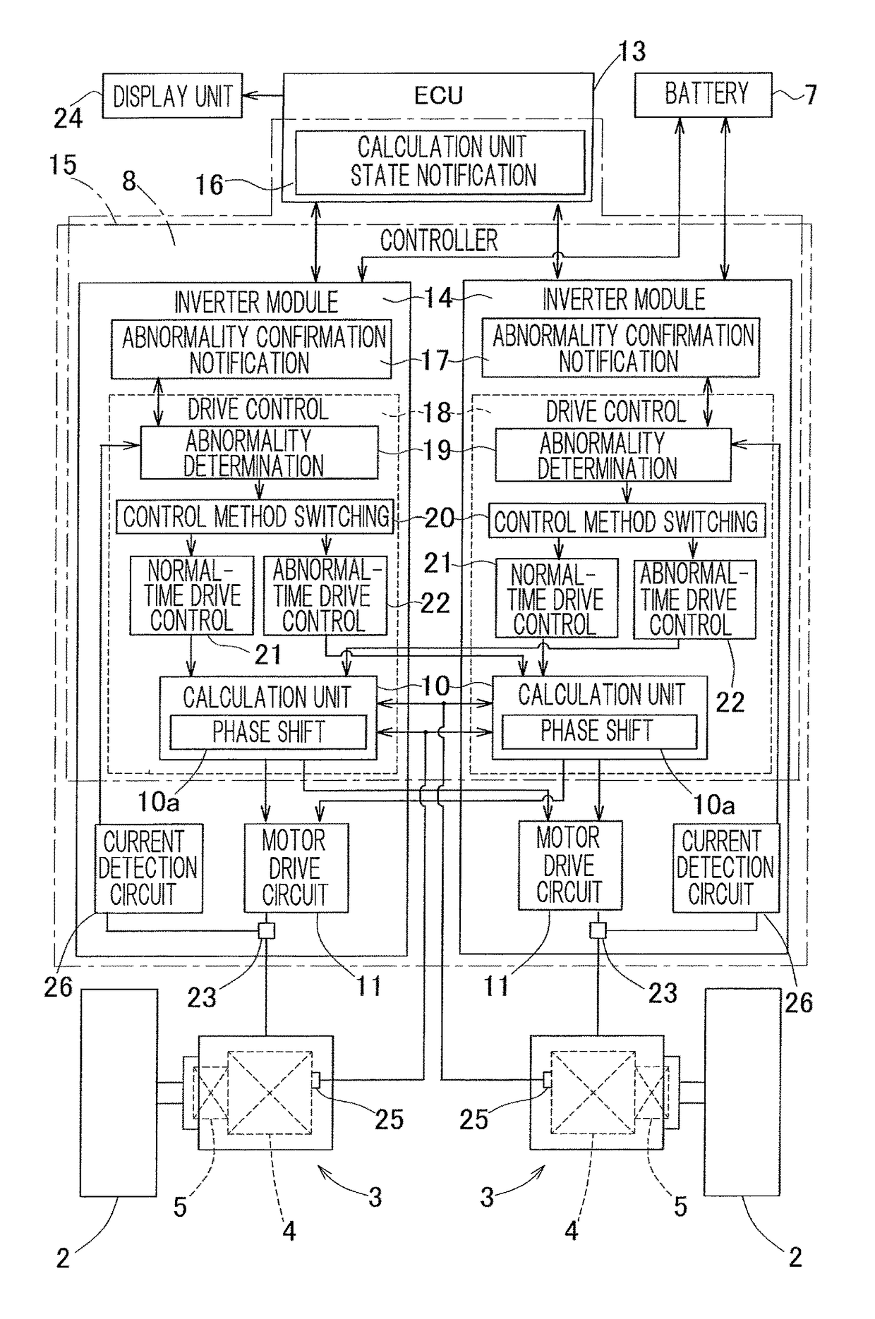
[0029]A motor drive device according to a first embodiment of the present invention will be described with reference to FIG. 1 to FIG. 6. The following description also includes a description regarding a method of controlling the motor drive device.

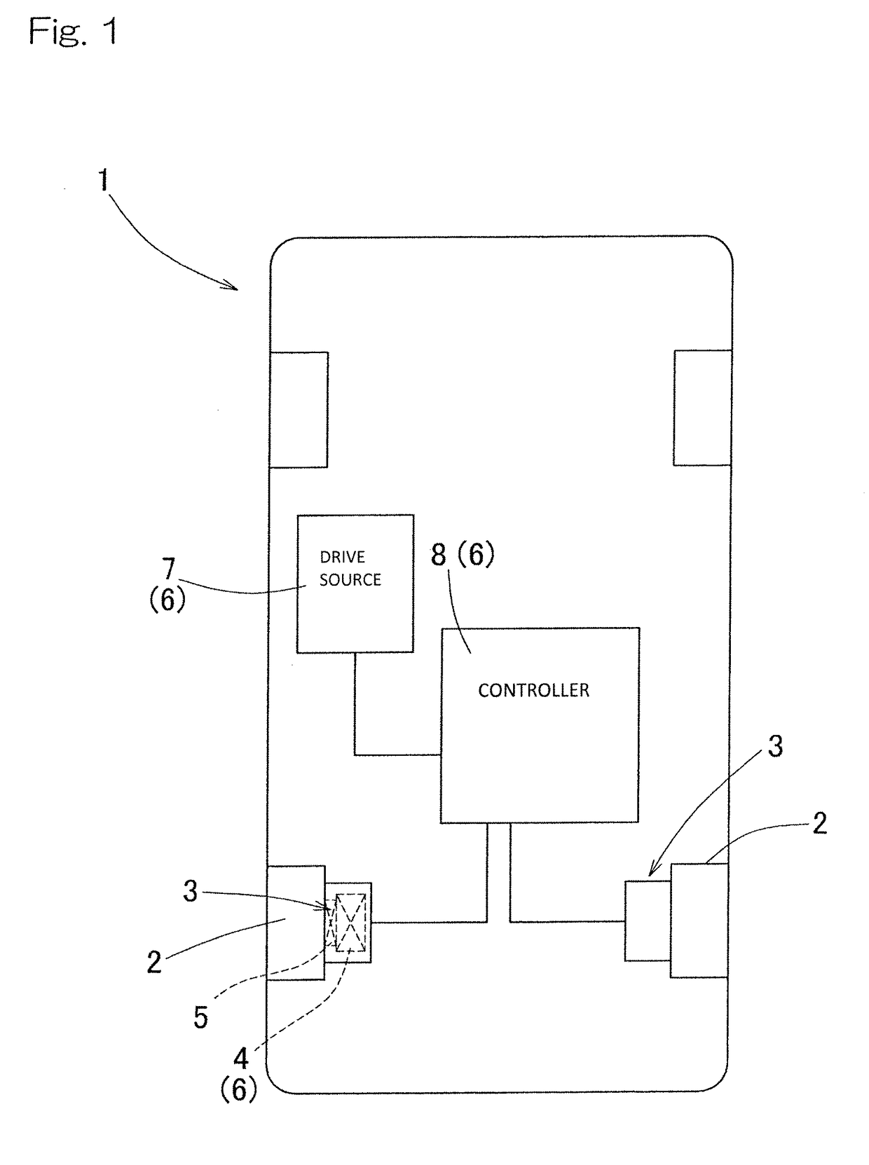
[0030]FIG. 1 is a diagram schematically showing the arrangement configuration of components in an electric vehicle equipped with the motor drive device of this embodiment. As shown in FIG. 1, the electric vehicle 1 includes in-wheel motor units 3, 3 disposed in left and right rear wheels 2, 2, respectively, which are drive wheels, and is driven to move with these in-wheel motor units 3, 3. It should be noted that a fuel cell vehicle may be used instead of the electric vehicle.

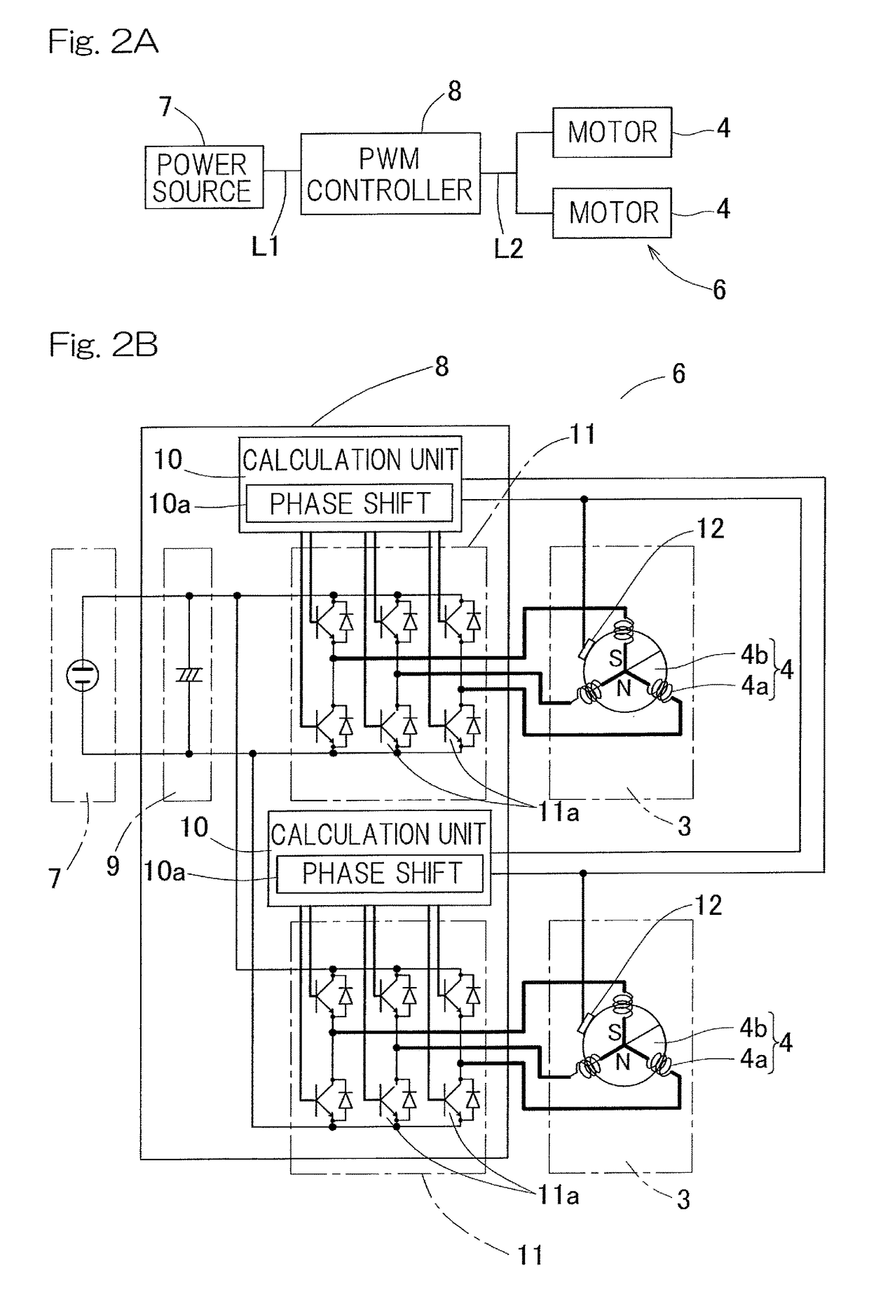
[0031]Each of the in-wheel motor units 3, 3 includes, for example, a motor 4, a reducer or reduction gear 5 which reduces the speed of rotation of the motor 4, and a wheel bearing which is not shown, and a part or the entirety of each in-wheel motor unit 3 is dispose...


PUM


Abstract

A motor drive device is provided which is able to reduce loss between a drive power source and a controller. The motor drive device includes a plurality of motors, a single drive power source which drives these motors, and a controller which controls energizing times during which motor coils of the plurality of motors are energized, by a PWM drive method. The controller includes phase shift portion which sets a PWM signal for causing a current to flow to the motor, into a phase different per motor. By the phase shift portion setting the PWM signal for causing a current to flow to the motor into a phase different per motor, so-called overlap of energizing times of currents is avoided.

Description

CROSS REFERENCE TO THE RELATED APPLICATION[0001]This application is a continuation application, under 35 U.S.C. §111(a), of international application No. PCT / JP2014 / 057125, filed Mar. 17, 2014, which is based on and claims Convention priority to Japanese patent application No. 2013-059403, filed Mar. 22, 2013, the entire disclosure of which is herein incorporated by reference as a part of this application.BACKGROUND OF THE INVENTION[0002]Field of the Invention[0003]The present invention relates to a motor drive device used in, for example, an electric vehicle in which a plurality of motors are driven with a single drive power source.[0004]Description of Related Art[0005]Hitherto, an electric vehicle has been proposed in which motors for driving left and right wheels, respectively, are driven with a single drive power source (Patent Document 1). A controller which controls these motors includes, for example, an inverter which converts DC power of the drive power source into three-pha...

Claims


Application Information

Patent Timeline
Patent Type & Authority Patents(United States)
IPC IPC(8): H02P5/00H02P5/74H02P5/46H02P27/08B60L3/00B60L15/08H02P6/06H02P6/08H02P25/022H02P25/22H02P27/06
CPCH02P27/08B60L3/0084B60L3/0092B60L15/08H02P5/46H02P5/74B60L2220/42B60L2220/44B60L2240/429Y02T10/644Y02T10/645Y02T10/648Y02T10/64
Inventor MASUDA, YUI
Owner NTN CORP
Why Eureka
Try Eureka