Extended temperature range mapping process of a furnace enclosure using various device settings

a technology of extended temperature range and furnace enclosure, which is applied in the direction of optical radiation measurement, image enhancement, instruments, etc., can solve the problems that the remaining surface and volume cannot be measured without sensors, and achieve the effect of effective temperature measurement of the entire furnace, maximum product yield, and maximum energy efficiency

Active Publication Date: 2017-07-04
HONEYWELL INT INC
View PDF35 Cites 4 Cited by
  • Summary
  • Abstract
  • Description
  • Claims
  • Application Information

AI Technical Summary

Benefits of technology

[0009]It is an important task for an operator to effectively perform temperature measurements of the entire furnace for maximum product yield, maximum energy efficiency, and minimum flue gas consumed. An image-capturing device generates a light intensity image of a selected region of the furnace. Transformation of the observed image intensity to a temperature reading is needed.

Problems solved by technology

However, the temperature sensors can measure only certain areas of the furnace where the sensors are installed, and thus the remaining surfaces and volumes cannot be measured without the sensors.

Method used


Image

  • Extended temperature range mapping process of a furnace enclosure using various device settings
  • Extended temperature range mapping process of a furnace enclosure using various device settings
  • Extended temperature range mapping process of a furnace enclosure using various device settings

Examples


Embodiment Construction

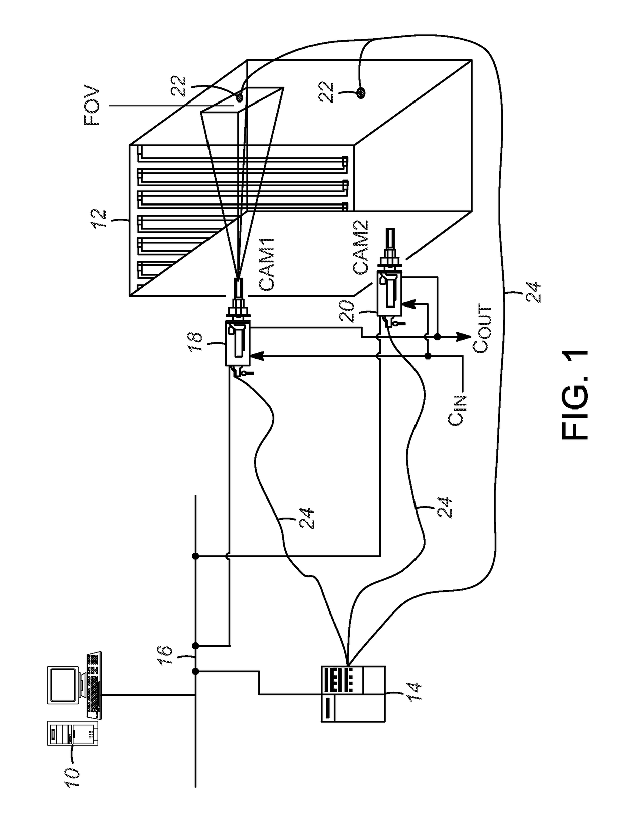
[0016]Referring now to FIG. 1, an exemplary mapping unit 10 using an embodiment of the present process is provided for accurately mapping temperatures of a selected region inside a large scale enclosure 12, such as an industrial furnace. As used herein, the term “unit” may refer to, be part of, or include an Application Specific Integrated Circuit (ASIC), an electronic circuit, a computer processor (shared, dedicated, or group) and / or memory (shared, dedicated, or group) that executes one or more software or firmware programs, a combinational logic circuit, and / or other suitable components that provide the described functionality. Thus, while this disclosure includes particular examples and arrangements of the units, the scope of the present system should not be so limited since other modifications will become apparent to the skilled practitioner.

[0017]The mapping unit 10 may reside in or be coupled to a server or computing device 14 (including, e.g., database and video servers), an...


PUM


Abstract

A process is provided for mapping temperatures in an enclosure during a combustion process. A device setting of an image-capturing device is provided. An intensity-temperature mapping is generated by performing an intensity-temperature calibration based on an intensity of an image pixel in a field of view (FOV) generated by the image-capturing device, a corresponding temperature measurement, and a selected device setting. Each emitted radiation of selected regions is detected based on a first image in the FOV. At least one region is determined whether the region is poor responsive, based on the intensity-temperature mapping associated with the device setting. The at least one poor responsive region is replaced with acceptable regions unaffected by the saturation from at least one other image captured at a different device setting for higher temperature resolution.

Description

[0001]The present invention relates generally to a process for estimating temperature readings of a furnace enclosure, and more particularly to an intensity to temperature mapping process for estimating a high dynamic temperature range of the furnace enclosure using various device settings of an image-capturing device.BACKGROUND OF THE INVENTION[0002]Accurately analyzing internal conditions of a furnace is an essential task for an operator to better control temperatures of different regions in a furnace enclosure for producing products more efficiently and saving energy-related costs. Typically, image-capturing devices, such as color cameras, infrared spectrometers, filtered cameras, and the like, are installed in the furnace enclosure for detecting the temperatures of the furnace enclosure. Intensities of image pixels received from the devices have a direct relationship with the temperatures of viewed surfaces inside the furnace.[0003]Such image-capturing devices provide a wide cov...

Claims


Application Information

Patent Timeline
Patent Type & Authority Patents(United States)
IPC IPC(8): G01J5/00G01J5/60G06T5/00G01J5/10G01J5/06
CPCG01J5/0044G01J5/602G06T5/005G06T5/008G01J2005/0048G01J2005/0077G01J2005/068G06T2207/10048G01J5/064G01J5/80
Inventor VENKATESHA, SHARATHAU, KWONG W.BIETTO, STEFANO
Owner HONEYWELL INT INC
Why Eureka
Try Eureka