
Thermal conductivity measurement apparatus and related methods

a technology measuring apparatus, which is applied in the direction of heat measurement, material thermal conductivity, instruments, etc., can solve the problems of difficult acquisition of transport properties along the length of very small specimens, macroscopic bodies, and inability to meet the requirements of thermal conductivity measuremen

Active Publication Date: 2017-07-04
THE UNITED STATES OF AMERICA AS REPRESETNED BY THE SEC OF THE AIR FORCE
View PDF2 Cites 31 Cited by
  • Summary
  • Abstract
  • Description
  • Claims
  • Application Information

AI Technical Summary

Benefits of technology

The present invention provides an apparatus and method for thermal conductivity measurement on micro and nano-scale test specimens. It solves problems and shortcomings of conventional thermal conductivity measurement methods. The apparatus includes a first heater assembly and a second heater assembly separated by a gap length. The method involves recording the temperature data of each heating element and RTD when no sample is placed, and then applying different power levels to maintain the desired temperature while the specimen is spanning the gap between the platen. The technical effects include improved accuracy and precision in thermal conductivity measurement, and simplified and efficient testing procedures.

Problems solved by technology

Current thermophysical measurement techniques experience difficulty in acquiring transport properties along the length of very small specimen (such as, by way of example, carbon nanotube “yarns”).
In fact, many new materials are designed and fabricated at the microscopic level and below, and do not have macroscopic bodies that can be tested with conventional thermal measurement apparatus.
In each of the cases noted above, traditional methods of measuring thermal conduction through a bulk material cannot be made, and they do not accurately reflect the thermophysical properties of the microscopic or nanoscopic constituents of a material or structure.
Though there is an abundance of theoretical studies on thermal transport properties of micro- and nano-structured materials, experimental measurement at these length scales are still challenging and thus scarce.
Conventional thermal measurement techniques with devices at the micro- and nano-meter length scales do not have sufficient spatial resolution to determine accurate temperature and resulting thermal conductivity.
While the noted conductivity measurement methods have their own merits, these indirect measurement techniques tend to yield qualitative rather than quantitative data and often rely on modeled localized thermal flow.
However, the 3ω method does not produce acceptable results for the thermal property measurements of freestanding microscale structures such as fibers.
Unfortunately, prior systems are only amenable to randomly oriented nanofibers that can be transported to the fixed gap between these heaters and there is no independent control of test temperature and heat flux.

Method used


Image

  • Thermal conductivity measurement apparatus and related methods
  • Thermal conductivity measurement apparatus and related methods
  • Thermal conductivity measurement apparatus and related methods

Examples


Embodiment Construction

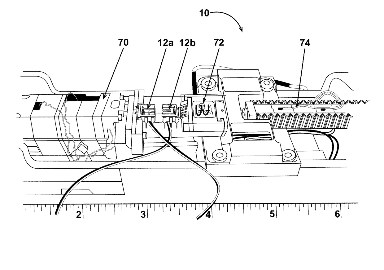
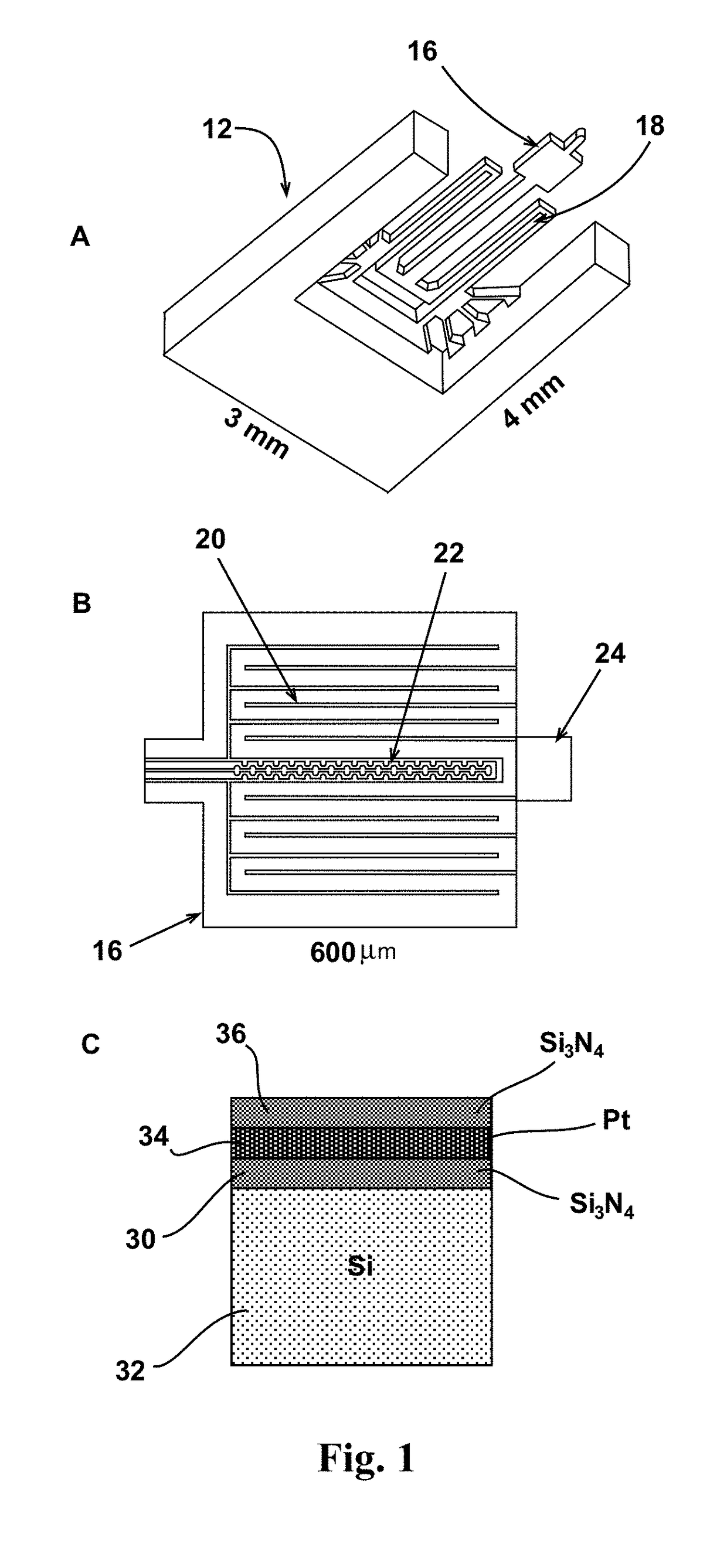
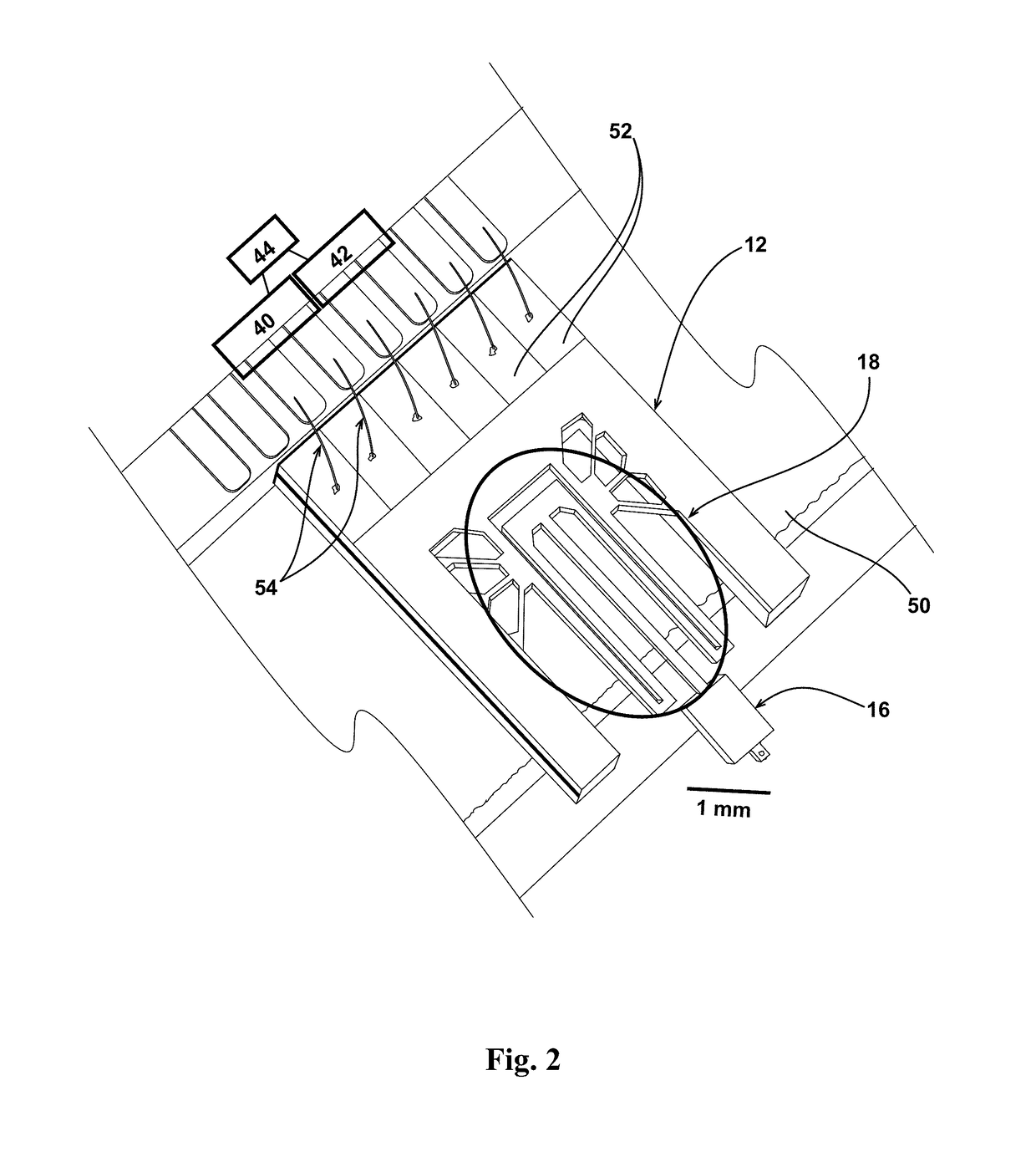
[0028]The discussion that follows is directed to a thermal property measurement apparatus and related methods for micro-scaled and nano-scaled structures. Furthermore, the disclosed invention enables thermal testing of specimens under no load, static load, and dynamic loading conditions. In one embodiment of the disclosed invention, two independently controlled micro-heaters are employed. Additionally, according to an embodiment of the inventive methodology, a first heater and second heater are held at a first desired temperature and a second desired temperature, respectively, above the ambient temperature. Then, a first power driving the first heater and a second power driving the second heater are allowed to automatically adjust, via computer control, so as to maintain the first desired temperature and the second desired temperature while a test specimen bridges the gap between the first heater and the second heater. This enables thermal measurements to be made in micron-sized sam...


PUM

PropertyMeasurementUnit
diametersaaaaaaaaaa
thicknessaaaaaaaaaa
temperatureaaaaaaaaaa

Abstract

An apparatus for thermal conductance measurement includes a first heater assembly having a beam, a platen disposed at an end of the beam, and a heating element and a Resistance Temperature Device (RDT) disposed on the platen. The embodiment further includes a second heater assembly having a second beam, a second platen disposed at an end of the second beam, and a second heating element and a second Resistance Temperature Device (RDT) disposed on the platen. A test rig is also included, and the first heater and second heater assembly are mated to the test rig and separated by a gap length.

Description

RIGHTS OF THE GOVERNMENT[0001]The invention described herein may be manufactured and used by or for the Government of the United States for all governmental purposes without the payment of any royalty.FIELD OF THE INVENTION[0002]The present invention relates generally to methods and apparatus for performing thermal conductivity measurements, and more particularly to performing such measurements on ultra-small test specimens.BACKGROUND OF THE INVENTION[0003]Current thermophysical measurement techniques experience difficulty in acquiring transport properties along the length of very small specimen (such as, by way of example, carbon nanotube “yarns”). Such materials have lateral dimensions of tens or hundreds of microns and exhibits substantially different thermal conduction in their axial and transverse orientations due its inherent directional lattice morphology. Modeling the bulk properties of composites containing micro-scale or nano-scale fibers or particulates requires knowledge...

Claims


Application Information

Patent Timeline
Patent Type & Authority Patents(United States)
IPC IPC(8): G01N25/18G01K7/18
CPCG01N25/18G01K7/186
Inventor ROY, AJIT KWHEELER, IV, ROBERTGANGULI, SABYASHACHI
Owner THE UNITED STATES OF AMERICA AS REPRESETNED BY THE SEC OF THE AIR FORCE
Learn More