
Method for testing a bar winding of a rotor of a rotating electrical machine

a technology of rotating electrical machines and windings, which is applied in the direction of temperature measurement of moving solids, instruments, dynamo-electric components, etc., can solve the problems of high current and power loss of rotor bars, insufficient thermal energy of rotors in particular, and short circuit rings, so as to improve thermal radiation, shorten testing timewise, and improve detection accuracy

Inactive Publication Date: 2017-07-04
SIEMENS AG
View PDF13 Cites 1 Cited by
  • Summary
  • Abstract
  • Description
  • Claims
  • Application Information

AI Technical Summary

Benefits of technology

This patent describes an invention that allows for detailed thermal stress monitoring of the rotor in an electrical machine. By using a thermal radiation sensor, the invention can detect overloading of the rotor and recognize areas of damage. The sensor can be placed in the stator and can achieve spatial resolution of individual bars of the rotor. The sensor is sensitive to infrared radiation and can detect changes in the rotor's temperature. The invention can also include a coating to improve thermal radiation detection. The measured thermal radiation values can be used to assess the rotor's load state and identify potential issues. Overall, the invention provides a reliable and efficient way to monitor the health of the rotor in an electrical machine.

Problems solved by technology

High currents and power losses in the rotor bars and short-circuit ring can occur in the process.
The thermal energy of the rotor in particular can only be dissipated very inadequately due to the machine construction if no further cooling effect is provided.
This can lead to a thermal overloading in particular in the case of renewed start-up of the electrical machine.
The heat is produced in the electrical machine during operation thereof substantially by the following sources of losses: current heat losses, magnetic reversal losses and friction losses.
The heat generated by the sources of losses leads to thermal stress on the electrical machine.
The ageing can lead to breaking of the connection point, whereby the electrical machine is ultimately unusable.
Different electrical bar resistances and transition resistances at the connection points also lead to imbalances in the current distribution in the rotor, whereby local temperature differences can occur at the surface of the rotor and moment swings may even be generated.

Method used


Image

  • Method for testing a bar winding of a rotor of a rotating electrical machine
  • Method for testing a bar winding of a rotor of a rotating electrical machine
  • Method for testing a bar winding of a rotor of a rotating electrical machine

Examples


Embodiment Construction

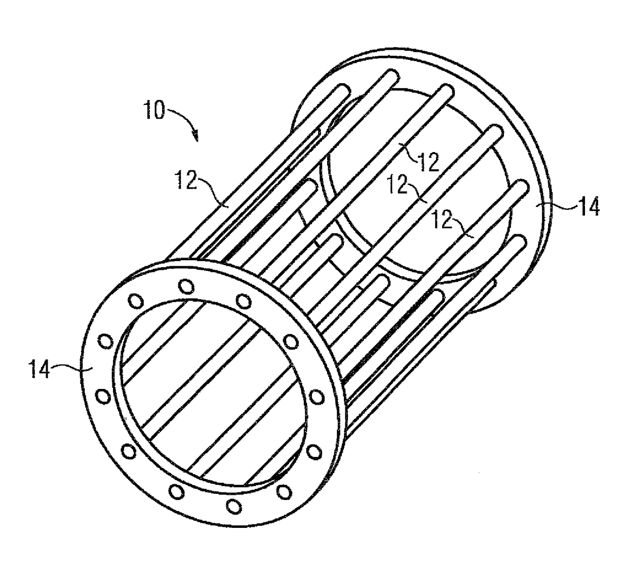
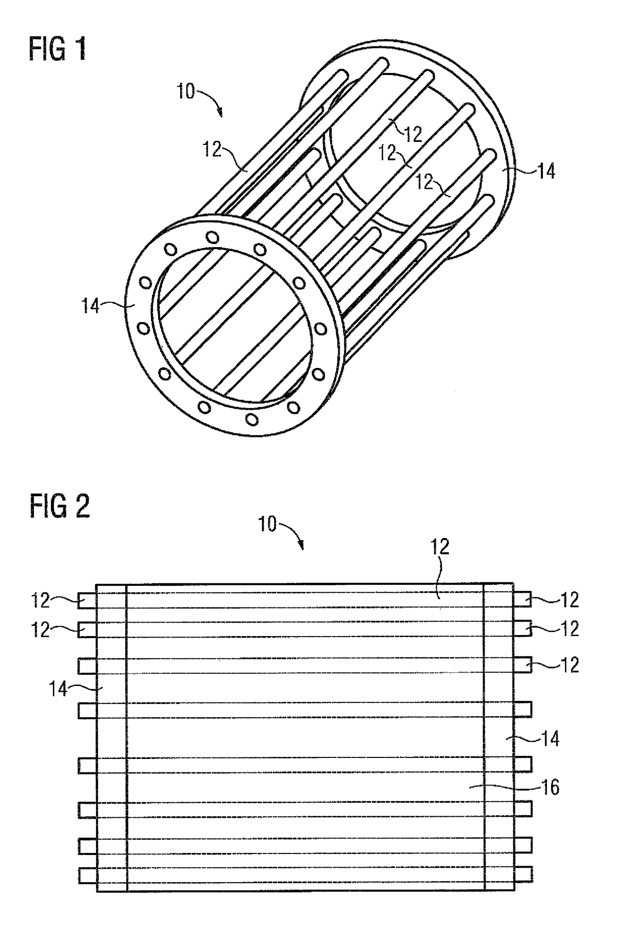
[0050]FIG. 1 shows in a perspective schematic view a rotor cage 10 of a rotor 20 of an asynchronous machine without core, with the rotor cage 10 having bars 12 which are each electroconductively connected at the ends to a short-circuit ring 14. In the present case both the bars 12 and the short-circuit ring 14 are formed from a copper alloy and the bars 12 soldered, welded or cast at the ends to the short-circuit ring 14. From the schematic side view of the rotor cage 10 in FIG. 2 it can be seen that at the ends the individual bars 12 penetrate slightly through the respective short-circuit ring 14.

[0051]In addition to the rotor cage 10FIG. 2 shows the core 16 which is made from insulated electrical sheets which are stacked to form the core 16. The core 16 does not have designated slots in which the bars 12 are arranged.

[0052]If the rotor constructed in this way is thermally stressed, the bars 12 expand in a different ways in relation to the core 16 and to the short-circuit ring 14. ...


PUM

PropertyMeasurementUnit
frequencyaaaaaaaaaa
areaaaaaaaaaaa
edge lengthaaaaaaaaaa

Abstract

In a method for testing a bar winding of a rotor of a rotating electrical machine, a rotor temperature is detected by a thermal radiation sensor, which is arranged in a stator of the rotating electrical machine. A thermal radiation sensor is used with a resolution suitable for the thermal detection of individual bars of the bar winding. The rotor is rotated at a speed that is lower than a limit frequency of the thermal radiation sensor divided by the number of bars of the bar winding, and the thermal radiation of the rotor is detected by the thermal radiation sensor. The thermal radiation sensor is sampled at a sampling frequency that is higher than the speed of the rotor multiplied by the number of bars and the sampled values of the thermal radiation sensor are evaluated.

Description

CROSS-REFERENCES TO RELATED APPLICATIONS[0001]This application is the U.S. National Stage of International Application No. PCT / EP2014 / 053191, filed Feb. 19, 2014, which designated the United States and has been published as International Publication No. WO 2014 / 146847 and which claims the priority of European Patent Application, Serial No. 13159840.1, filed Mar. 19, 2013, pursuant to 35 U.S.C. 119(a)-(d).BACKGROUND OF THE INVENTION[0002]The present invention relates to a method for testing a bar winding of a rotor of a rotating or linearly moved electrical machine, wherein thermal radiation of the rotor is detected by means of a thermal radiation sensor arranged in a stator or the rotating electrical machine. The invention also relates to a device for testing a bar winding of a rotor of a rotating electrical machine, having a thermal radiation sensor, arranged in a stator of the rotating electrical machine, by means of which thermal radiation of the rotor can be detected.[0003]An el...

Claims


Application Information

Patent Timeline
Patent Type & Authority Patents(United States)
IPC IPC(8): G01R31/34G01K13/08H02K15/00H02K11/25H02K17/16
CPCG01R31/346G01K13/08G01R31/343H02K11/25H02K15/00H02K17/16
Inventor ZETTNER, JURGENDEEG, CHRISTIANSCHUHMANN, THOMAS
Owner SIEMENS AG
Learn More