Generating approximate usage measurements for shared cache memory systems

a cache memory and approximation technology, applied in the direction of memory adressing/allocation/relocation, instruments, sustainable buildings, etc., can solve the problems of reducing the overall performance of the cache, affecting the overall performance, and reducing the space-efficient mechanism of monitoring the usage of the cache, so as to reduce storage overhead and minimize the impact on processor performance and power consumption.

Inactive Publication Date: 2017-07-04
QUALCOMM INC
View PDF8 Cites 0 Cited by
  • Summary
  • Abstract
  • Description
  • Claims
  • Application Information

AI Technical Summary

Benefits of technology

[0008]The cache usage monitor is further configured to generate an approximate usage measurement for a QoS class of the plurality of QoS classes based on the plurality of QoSID tracking tags. By trading off accuracy of the cache usage measurement for a reduction in storage overhead for the plurality of QoSID tracking tags, the shared cache memory system may provide sufficient usage measurement data for managing cache allocation, while minimizing impacts on processor performance and power consumption.

Problems solved by technology

Resource interference and conflicts between computer hardware units could result in negative consequences, such as missing a real-time deadline on a mobile System-on-Chip (SoC), or violating a Service Level Agreement (SLA) on a consolidated server, as non-limiting examples.
Additionally, reference streams associated with some computer hardware units may have little temporal locality, leading to cache pollution and a negative impact on overall performance if left unchecked.
However, conventional cache memory systems do not provide a space-efficient mechanism for monitoring cache usage.
As a result, such conventional cache memory systems may remain underutilized to protect against worst case performance in the presence of cache interference.
Moreover, a lack of feedback regarding cache occupancy may result in computer processing systems being unable to provide optimal scheduling of system tasks.

Method used


Image

  • Generating approximate usage measurements for shared cache memory systems
  • Generating approximate usage measurements for shared cache memory systems
  • Generating approximate usage measurements for shared cache memory systems

Examples


Embodiment Construction

[0016]With reference now to the drawing figures, several exemplary aspects of the present disclosure are described. The word “exemplary” is used herein to mean “serving as an example, instance, or illustration.” Any aspect described herein as “exemplary” is not necessarily to be construed as preferred or advantageous over other aspects.

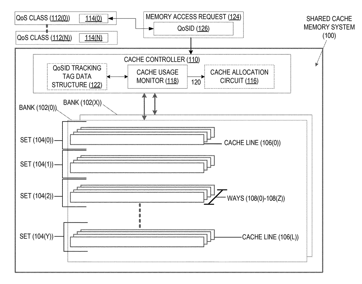
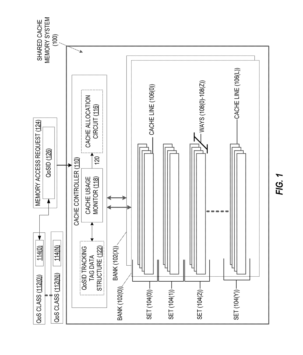
[0017]In this regard, FIG. 1 is provided to illustrate a structure of a shared cache memory system 100. The shared cache memory system 100 may be provided in a semiconductor die, as a non-limiting example. In some aspects, the shared cache memory system 100 may be a level 1 (L1) cache, a level 2 (L2) cache, or a level 3 (L3) cache, among others, in a hierarchy of memories (not shown). In the example of FIG. 1, the shared cache memory system 100 is a memory array organized into banks 102(0)-102(X). Each of the banks 102(0)-102(X) comprises one or more sets 104(0)-104(Y), with each of the sets 104(0)-104(Y) made up of a subset of cache lines 106(0)-106(...


PUM


Abstract

Generating approximate usage measurements for shared cache memory systems is disclosed. In one aspect, a cache memory system is provided. The cache memory system comprises a shared cache memory system. A subset of the shared cache memory system comprises a Quality of Service identifier (QoSID) tracking tag configured to store a QoSID tracking indicator for a QoS class. The shared cache memory system further comprises a cache controller configured to receive a memory access request comprising a QoSID, and is configured to access a cache line corresponding to the memory access request. The cache controller is also configured to determine whether the QoSID of the memory access request corresponds to a cache line assigned to the QoSID. If so, the cache controller is additionally configured to update the QoSID tracking tag.

Description

PRIORITY CLAIM[0001]The present application claims priority under 35 U.S.C. §119(e) to U.S. Provisional Patent Application Ser. No. 62 / 084,469 filed on Nov. 25, 2014, and entitled “GENERATING APPROXIMATE USAGE MEASUREMENTS FOR SHARED CACHE MEMORY, AND RELATED METHODS AND SYSTEMS,” the contents of which is incorporated herein by reference in its entirety.BACKGROUND[0002]I. Field of the Disclosure[0003]The technology of the disclosure relates generally to shared cache memory systems, and, in particular, to measuring usage of shared caches.[0004]II. Background[0005]An increasing number of computer hardware units (e.g., central processing units (CPUs), graphics processing units (GPUs), digital signal processing (DSP) units, and / or direct memory access (DMA) engines, as non-limiting examples) are configured to share memory system resources such as caches, memory, interconnect bandwidth, and cache bandwidth. Resource interference and conflicts between computer hardware units could result ...

Claims


Application Information

Patent Timeline
Patent Type & Authority Patents(United States)
IPC IPC(8): G06F12/08G06F12/0846G06F12/084G06F11/34G06F12/0864G06F12/0895
CPCG06F12/084G06F11/3466G06F11/3471G06F12/0846G06F12/0848G06F11/348G06F12/0864G06F12/0895G06F2201/88G06F2201/885G06F2212/1016G06F2212/1044G06F2212/2112G06F2212/282G06F2212/314Y02B60/1225G06F11/3037G06F11/3433Y02D10/00
Inventor HOWER, DEREK ROBERTCAIN, III, HAROLD WADE
Owner QUALCOMM INC
Why Eureka
Try Eureka